
A2
| Oil pump and retaining frame - exploded view |
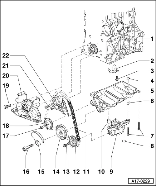
| 1 - | Cylinder block |
| 2 - | Oil spray jet |
| q | For piston cooling |
| q | Note installation position: Turn oil spray jet anti-clockwise until it makes contact with cylinder block and secure in this position |
| 3 - | Bolt |
| q | Insert without sealant |
| q | 27 Nm |
| 4 - | O-ring |
| q | Renew |
| 5 - | Retaining frame |
| q | Before installing, check that the fitting sleeve for centring on cylinder block is in place and that the O ring is inserted in the retaining frame. |
| q | Removing and installing → Chapter |
| 6 - | Dowel sleeve |
| 7 - | Bolt |
| q | Oil pump to retaining frame, 20 Nm + 90° (1/4 turn) further; renew bolt |
| q | Retaining frame to cylinder block: 14 Nm +180° (1/2 turn) further; renew bolt |
| 8 - | O-ring |
| q | Renew |
| q | Check for firm attachment |
| q | Oil lightly when fitting |
| 9 - | Oil pump |
| q | With pressure relief valve (11.5 bar) |
| q | Removing and installing → Chapter |
| q | Before installing, check that the two dowel sleeves for centralising are fitted. |
| 10 - | Dowel sleeve |
| 11 - | Chain |
| q | Note installation position → Chapter „Removing and installing balance shaft and retaining frame“ |
| 12 - | Chain sprocket for oil pump |
| 13 - | Bolt |
| q | Renew |
| q | 20 Nm +90° (1/4 turn further) |
| 14 - | Chain sprocket for balance shaft |
| q | Can only be installed in one position |
| 15 - | Balance weight |
| q | Can only be installed in one position |
| 16 - | Bolt |
| q | Renew |
| q | Use socket -T10061- to loosen and tighten |
| q | 100 Nm +90° (1/4 turn further) |
| 17 - | Bolt |
| q | 20 Nm |
| 18 - | Idler sprocket |
| 19 - | Bolt |
| q | 15 Nm |
| 20 - | Sealing flange (pulley end) |
| q | Must be positioned on dowel sleeves |
| q | Removing and installing → Chapter |
| q | Renewing crankshaft oil seal on pulley end → Chapter |
| 21 - | Bolt |
| q | Renew |
| q | 8 Nm +90° (1/4 turn further) |
| 22 - | Chain tensioner with tensioning rail |
| q | To remove lock with locking pin -T10060 A- |
| q | Removing and installing → Chapter „Removing and installing balance shaft and retaining frame“ |