audi Workshop Repair Guides

Audi Workshop Service and Repair Manuals

Crankshaft > < Balance shaft and retaining frame - exploded view
Removing and installing balance shaft and retaining frame
Special tools and workshop equipment required
   
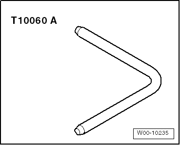
t  Locking pin -T10060 A-
  W00-10235
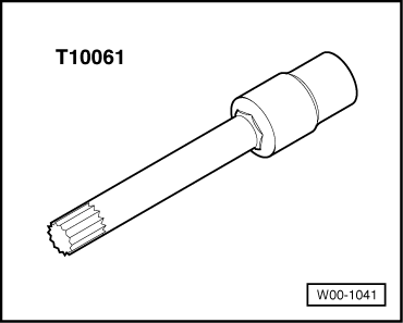
t  Socket -T10061-
Removing
–  Remove poly V-belt → Chapter.
–  Remove toothed belt: toothed belt drive with hydraulically damped tensioning roller → Chapter, toothed belt drive with friction-damped tensioning roller → Chapter.
–  Remove sump → Chapter.
–  Remove sealing flange (pulley end) → Chapter.
  W00-1041
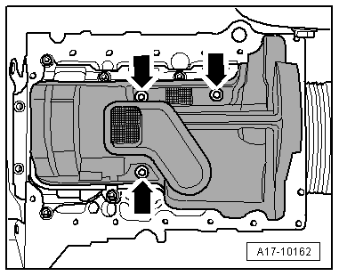
–  Remove bolts -arrows-.
–  Release the 5 retaining tabs and remove baffle plate.
  A17-10162
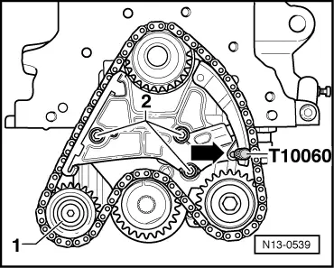
–  Press down chain tensioner and lock with locking pin -T10060 A--arrow-.
–  Unbolt idler sprocket -1- from retaining frame.
–  Unscrew bolts -2- and remove chain tensioner.
–  Remove chain from sprockets and lay it aside on a clean surface.
  N13-0539
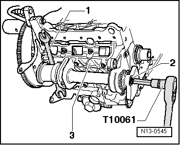
–  Block balance shaft as shown using a spanner (24/27 mm) -item 1-.
l  When blocking the balance shaft, make sure that the spanner is centred on the balance weight and at right angles to the balance shaft.
–  Loosen bolt -2- at balance weight using socket -T10061-.
  Note
Do not unscrew bolt all the way when loosening.
–  Unbolt retaining frame -3- from cylinder block and remove retaining frame with balance shaft.
–  Lay retaining frame aside on a clean surface.
–  Unscrew bolt on balance weight and detach balance weight and chain sprocket.
–  Turn balance shaft so that it can be removed from the bearings.
Installing
Installation is carried out in the reverse order; note the following:
  Note
t  Renew O-ring.
t  Renew the bolts tightened with specified tightening angle.
–  Lubricate contact surfaces of bearing and insert balance shaft.
–  Fit chain sprocket and balance weight on balance shaft.
  Note
Chain sprocket and balance weight can only be fitted in one position.
–  Tighten bolt for balance weight/chain sprocket hand-tight.
–  Check that dowel sleeve in cylinder block and O-ring in retaining frame are in position before installing retaining frame.
  N13-0545
–  Tighten retaining frame -3- to cylinder block hand-tight and align.
l  Check that retaining frame aligns flush with outer edge of cylinder block on pulley end.
–  Tighten retaining frame in stages and in diagonal sequence.
–  Block balance shaft as shown using a spanner (24/27 mm) -item 1-.
l  When blocking the balance shaft, make sure that the spanner is centred on the balance weight and at right angles to the balance shaft.
–  Secure balance weight using new bolt -2-.
–  Install chain tensioner.
  N13-0545
–  Clean chain with a lint-free cloth.
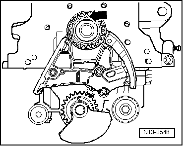
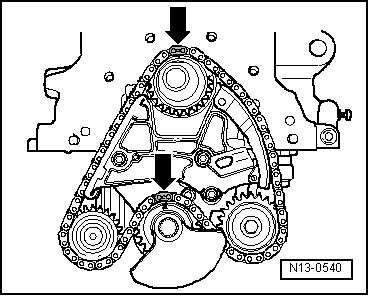
–  Ensure that mark -arrow- on crankshaft sprocket is at top.
  N13-0546
–  Lay chain over crankshaft sprocket, oil pump sprocket and balance shaft sprocket.
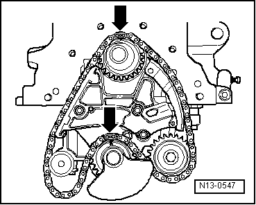
l  Ensure that marks on crankshaft sprocket and balance shaft sprocket align with the colour-coded chain links -arrows-.
  Note
The colour-coded chain links are additionally marked with a notch.
–  Engage idler sprocket in chain and tighten idler sprocket to retaining frame.
–  Remove locking pin from chain tensioner.
  N13-0547
–  Check that marks on crankshaft sprocket and balance shaft sprocket align with the colour-coded chain links -arrows-.
–  Install sealing flange (pulley end) → Chapter.
–  Fit baffle plate with new O-ring. To do this:
l  Lubricate O-ring with oil.
l  Lubricate sleeve on inside of baffle plate with oil.
l  Make sure sealing tape is properly applied.
l  Make sure baffle plate engages properly in retaining frame.
–  Install sump → Chapter.
–  Install toothed belt (adjust valve timing): toothed belt drive with hydraulically damped tensioning roller → Anchor, toothed belt drive with friction-damped tensioning roller → Anchor.
–  Install poly V-belt → Chapter.
Tightening torques
  N13-0540
ComponentNm
Retaining frame with balance shaft to cylinder block14 + 180° 1)2)
Balance weight with chain sprocket to retaining frame100 + 90° 1)3)
Chain tensioner to retaining frame8 + 90° 1)3)
Idler sprocket to retaining frame20
Baffle plate to retaining frame5
l  1) Renew bolt(s).
l  2) 180° = one half turn.
l  3) 90° = one quarter turn.


Crankshaft > < Balance shaft and retaining frame - exploded view