
A2
| Diagram of vacuum hose connections |
| Vehicles with engine code letters AMF |
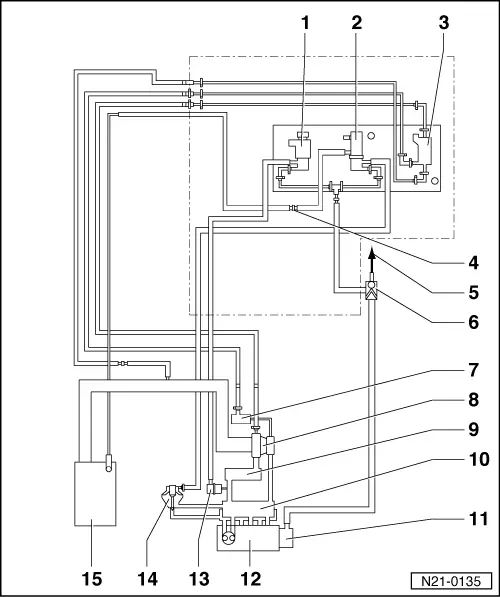
| 1 - | Variable intake manifold flap change-over valve -N239- |
| 2 - | Exhaust gas recirculation valve -N18- |
| 3 - | Solenoid valve for charge pressure control -N75- |
| 4 - | Connecting piece |
| 5 - | To brake servo |
| 6 - | Non-return valve |
| 7 - | Vacuum unit for charge pressure control |
| 8 - | Turbocharger |
| 9 - | Charge air cooler |
| 10 - | Intake manifold |
| 11 - | Tandem pump |
| q | For fuel and vacuum supply |
| 12 - | Cylinder head |
| 13 - | Vacuum unit for intake manifold flap |
| 14 - | Mechanical exhaust gas recirculation valve |
| q | Is combined with intake manifold connection |
| q | Can only be renewed together with intake manifold connection |
| 15 - | Air mass meter -G70- |
| Vehicles with engine code letters ATL, BHC |
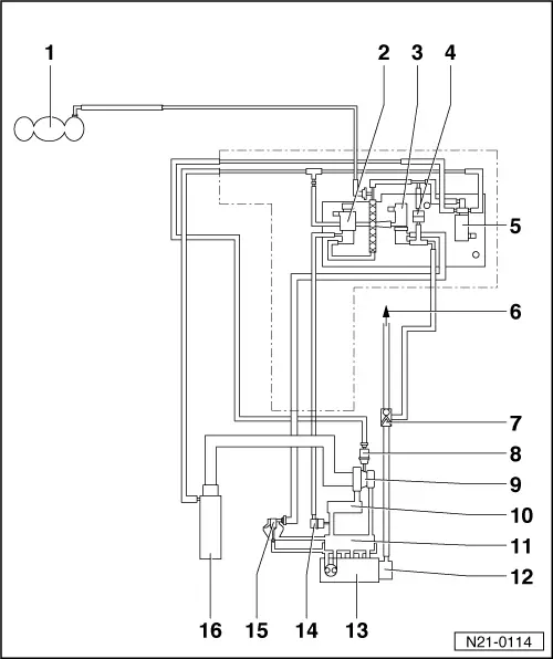
| 1 - | Vacuum reservoir |
| 2 - | Throttle butterfly valve -N211- |
| 3 - | Exhaust gas recirculation valve -N18- |
| q | Only for vehicles with engine code BHC |
| 4 - | Non-return valve |
| q | White connection to charge pressure control solenoid valve -N75- |
| 5 - | Solenoid valve for charge pressure control -N75- |
| 6 - | To brake servo |
| 7 - | Non-return valve |
| 8 - | Vacuum unit for charge pressure control |
| 9 - | Turbocharger |
| 10 - | Charge air cooler |
| 11 - | Intake manifold |
| 12 - | Tandem pump |
| q | For fuel and vacuum supply |
| 13 - | Cylinder head |
| 14 - | Vacuum unit for intake manifold flap |
| q | Only for vehicles with engine code BHC |
| 15 - | Mechanical exhaust gas recirculation valve |
| q | Is combined with intake manifold connection |
| q | Can only be renewed together with intake manifold connection |
| 16 - | Air cleaner |