audi Workshop Repair Guides

Audi Workshop Service and Repair Manuals

Removing and installing coolant temperature senderG62 > < Removing and installing map-controlled engine cooling thermostatF265
Removing and installing thermostat housing and coolant pipe (rear)
   
Removing
–  Drain coolant → Chapter.
–  Disconnect coolant hoses -arrows- from coolant expansion tank and move coolant hose (top) clear.
  A10-0802
–  Unplug electrical connector -1- at coolant shortage indicator switch -F66-.
–  Remove nut -arrow- and detach coolant expansion tank.
  A19-10671
–  Move B+ wire -1- clear at bracket.
–  Move engine wiring harness -2- clear at cable support bracket -arrow- and move to side.
  A10-10962
  Caution
Risk of damage to cable end-pieces.
Do not detach cable end-pieces from selector shaft lever or gear selector relay lever. The cable end-pieces must always be renewed if they have been detached.
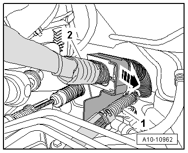
Release cable end-pieces for gear selector cable and gate selector cable as follows:
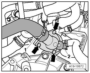
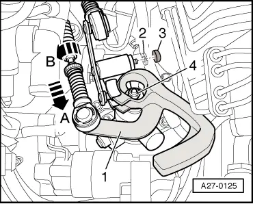
–  Press locking mechanism on selector cable to front as far as stop -arrow A-.
–  Turn locking sleeve as far as stop -arrow B- and lock in position.
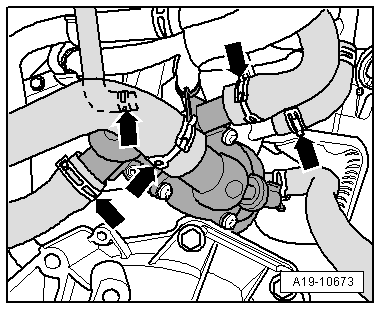
–  Pull gear selector cable and gate selector cable out of cable end-pieces.
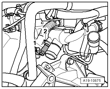
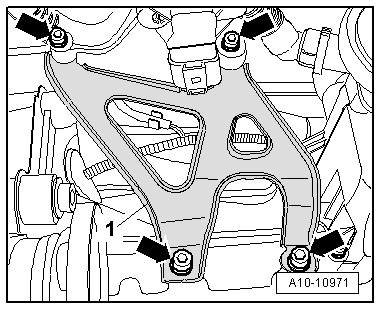
–  Detach cover cap -3- from securing clip.
–  Pull out securing clip -2- and detach relay lever.
  Note
Disregard -items 1 and 4-.
–  Detach drive shaft (right-side) from flange shaft of gearbox.
  A27-0125
–  Remove bolts -arrows- and detach intake manifold support.
  A10-10971
–  Unplug electrical connector -2-.
  Note
Disregard items marked -1- and -arrows-.
  A19-10672
–  Detach coolant hoses -arrows-.
  A19-10673
–  Unplug electrical connector -1- at coolant temperature sender -G62-.
  Note
Disregard item -2-.
–  Move electrical wiring on coolant pipe (rear) clear.
  A19-10675
–  Place drip tray for workshop hoist -VAS 6208- beneath engine.
–  Remove bolts -arrows- and carefully detach thermostat housing with coolant pipe (rear) from cylinder block and remove.
  A19-10674
–  Detach retaining clip -2- and detach coolant pipe (rear) -3- from housing -1- for thermostat -arrow-.
Installing
l  Tightening torque → Chapter
Installation is carried out in the reverse order; note the following:
  Note
t  Renew gaskets and O-rings.
t  Secure all hose connections with the correct type of hose clips (same as original equipment) → Parts catalogue.
  A19-10514
–  Fit new O-ring -4- and insert coolant pipe in thermostat housing.
l  Lug -3- must engage in U-shaped recess -2-.
–  Secure coolant pipe with retaining clip -1-.
–  Clean and smoothen sealing surface for O-ring in cylinder head.
–  Lubricate O ring with coolant additive.
–  Install intake manifold support → Rep. gr.24.
–  Install drive shaft (right-side) → Rep. gr.40.
–  Install and adjust gear selector cable and gate selector cable → Rep. gr.34.
–  Fill up with coolant → Anchor.
  A19-10676

Removing and installing coolant temperature senderG62 > < Removing and installing map-controlled engine cooling thermostatF265