audi Workshop Repair Guides

Audi Workshop Service and Repair Manuals

Checking compression > < Cylinder head - exploded view
Removing and installing cylinder head
Special tools and workshop equipment required
   
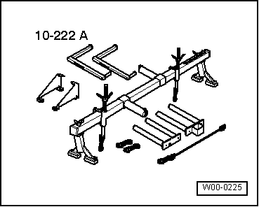
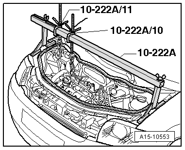
t  Support bracket -10 - 222 A-
  W00-0225
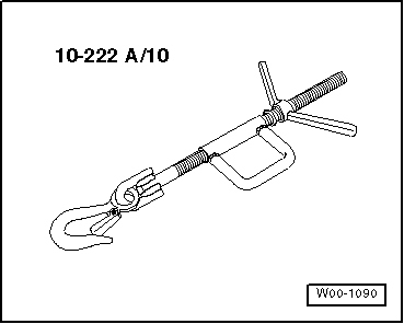
t  Hook -10 - 222 A /10-
  W00-1090
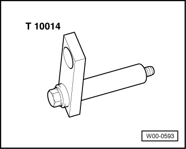
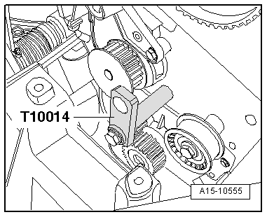
t  Retainer -T10014-
t  Sealant remover, commercially available
t  Sealant → Electronic parts catalogue
Removing
–  Drain coolant → Chapter.
–  Remove intake manifold → Rep. gr.24.
–  Set crankshaft to „TDC“ and lock camshafts with locking pins -T10074- → Chapter „Checking valve timing“.
  W00-0593
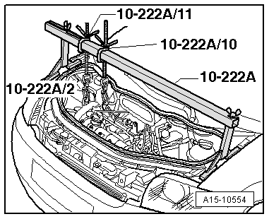
–  Position support bracket -10 - 222 A- with hook -10 - 222 A /10- and spindle -10 - 222 A /11- on bolted flanges of wing panels as shown in illustration.
l  Spindles are located at the rear.
–  Attach snap element of hook -10 - 222 A /10- to engine lifting eye (right-side).
  Note
The spindle -10 - 222 A /11- is used at a later stage.
–  Remove main drive toothed belt → Chapter.
–  Remove camshaft housing → Chapter.
  A15-10553
  WARNING
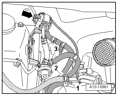
Risk of injury - fuel system operates under high pressure.
Wrap a clean cloth around the connection and carefully loosen the connection to allow the residual pressure to dissipate.
–  Detach fuel hoses -1- and -3-.
–  Disconnect hose -2- from activated charcoal filter.
  Note
Disregard -arrow-.
  A10-10961
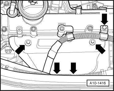
–  Remove bolts -arrows- and detach heat shield.
  A10-1416
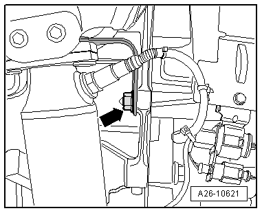
–  Unscrew nut -arrow- securing bracket for exhaust manifold.
  A26-10621
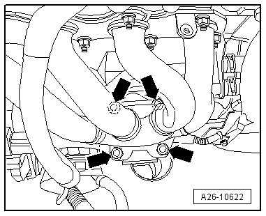
–  Remove nuts -arrows- securing starter catalytic converter to exhaust manifold.
–  Detach bracket for exhaust manifold.
  A26-10622
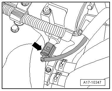
–  Unplug electrical connector -arrow- on oil pressure switch -F1-.
  A17-10347
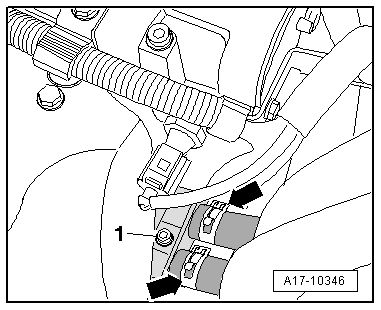
–  Remove bolt -1- securing bracket for coolant supply and return lines at oil cooler and detach together with retainer.
  Note
Disregard -arrows-.
  A17-10346
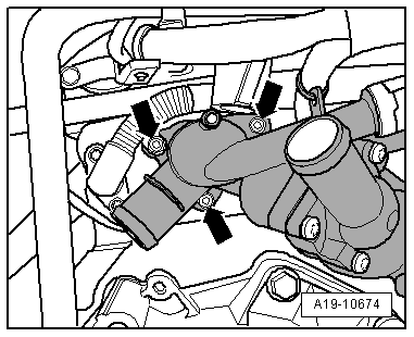
–  Remove bolts -arrows- for thermostat housing.
  A19-10674
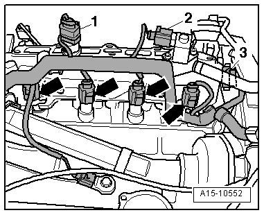
–  Unplug electrical connectors -1 , 2, 3- and -arrows- and move electrical wiring harness at cylinder head clear.
  A15-10552
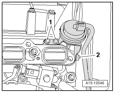
–  Remove bolts -1- and loosen bolt -2-.
–  Push vacuum unit for intake manifold flap slightly towards the rear.
  A15-10546
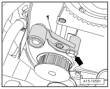
–  Remove bolt -arrow- and take off idler roller -1- for main drive toothed belt.
  A15-10581
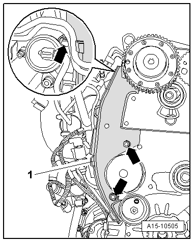
–  Remove bolts -arrows- and remove rear cover -1- for toothed belt.
  A15-10505
–  Secure retainer -T10014- in threaded hole in cylinder block as shown in illustration and tighten to 40 Nm.
  A15-10555
–  Attach spindle -10 - 222 A /11- with hook -10 - 222 A /2- onto retainer -T10014- at right.
–  Take up weight at spindle, detach hook -10 - 222 A /10- and move to side.
  A15-10554
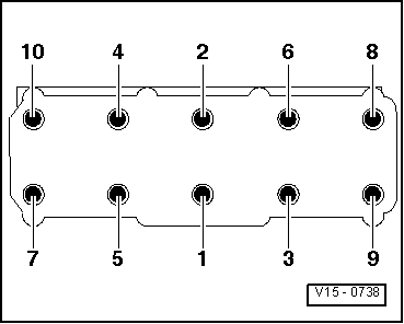
–  Slacken cylinder head bolts in the sequence -1 ... 10-.
–  Remove bolts and carefully take off cylinder head.
–  Place cylinder head onto soft surface (foam plastic).
Installing
l  Tightening torques → Chapter
  Caution
Avoid damage to sealing surfaces.
t  Carefully remove sealant residue from cylinder head and cylinder block.
t  Ensure that no long scores or scratches are made on the surfaces.
Avoid damage to cylinder block.
No oil or coolant must be allowed to remain in the blind holes for the cylinder head bolts in the cylinder block.
Risk of leaks at cylinder head gasket.
t  Carefully remove any sealant residue from the cylinder head and cylinder block. Ensure that no long scores or scratches are made on the surfaces.
t  Carefully remove any remaining emery and abrasive material.
t  Do not remove new cylinder head gasket from packaging until it is ready to be fitted.
t  Handle the cylinder head gasket very carefully to prevent damage to the silicone coating or the indented area of the gasket.
Avoid damage to open valves.
When installing an exchange cylinder head, the plastic protectors fitted to protect the open valves should not be removed until the cylinder head is ready to be fitted.
  Note
t  Renew the bolts tightened with specified tightening angle.
t  Renew self-locking nuts as well as seals, gaskets and O-rings.
t  Renew oil strainer in cylinder head.
t  When installing an exchange cylinder head, the contact surfaces between the hydraulic compensation elements, roller rocker fingers and cams must be oiled before installing the camshaft housing.
t  Secure all hose connections with the correct type of hose clips (same as original equipment) → Electronic parts catalogue.
t  After fitting a new cylinder head or cylinder head gasket, change the engine oil and the coolant in the entire cooling system.
  Caution
Protect lubrication system and bearings against contamination.
Cover exposed parts of the engine.
–  Remove sealant residue on cylinder head and camshaft housing using commercially available sealant remover.
–  Clean sealing surfaces; they must be free of oil and grease.
  N15-0026
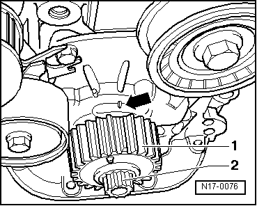
–  Check „TDC“ position of crankshaft:
l  The flat tooth on crankshaft sprocket -1- must align with marking -arrow- on oil pump housing.
  Note
Disregard item -2-.
–  Turn back crankshaft in opposite direction of engine rotation by approx. 45° from this position.
–  Fit seal for thermostat housing.
–  Place cylinder head gasket in position.
l  Note position of dowel sleeves in cylinder block.
l  Check installation position of cylinder head gasket: the word „oben“ (top) or the Part No. should be visible.
–  Fit cylinder head.
  N17-0076
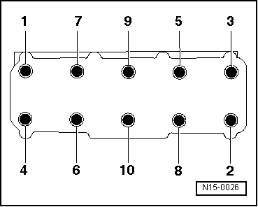
–  Tighten cylinder head bolts → Fig..
  Note
Cylinder head bolts do not have to be torqued down again later after repair work.
Remaining installation steps are carried out in reverse sequence; note the following:
–  Install cover (rear) for toothed belt → Chapter.
–  Install idler roller for main drive toothed belt → Chapter.
–  Install vacuum unit for intake manifold flap → Rep. gr.24.
–  Install thermostat housing → Chapter.
–  Install bracket for exhaust manifold and heat shield → Chapter.
–  Install camshaft housing → Chapter.
–  Install main drive toothed belt → Chapter.
–  Install intake manifold → Rep. gr.24.
–  Change engine oil → Booklet809.
–  Fill cooling system with fresh coolant → Chapter.
  V15-0738

Checking compression > < Cylinder head - exploded view