audi Workshop Repair Guides

Audi Workshop Service and Repair Manuals

Servicing tandem pump > < Checking fuel gauge sender G
Removing and installing fuel gauge senderG
Removing and installing fuel gauge sender -G-
Special tools and workshop equipment required
   
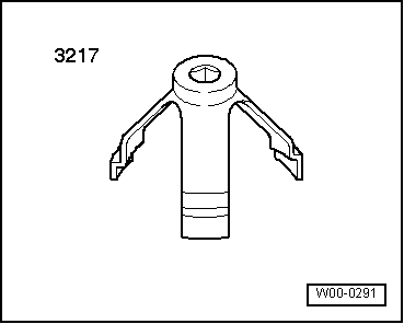
t  Spanner for union nuts -3217-
Removing
Observe safety precautions → Chapter.
Observe rules for cleanliness → Chapter.
l  The fuel tank must not be more than 3/4 full when removing the fuel gauge sender. Drain the tank if necessary. Procedure → Chapter.
  W00-0291
–  Fold down the rear seat bench or remove the rear seat bench → Rep. Gr.72.
–  Fold back lining under rear set.
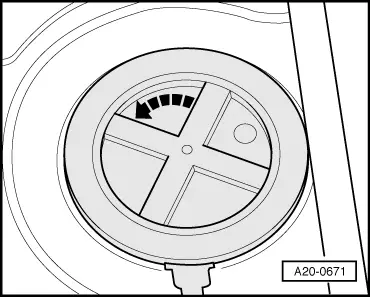
–  Turn cover for fuel gauge sender in -direction of arrow- and detach cover.
  A20-0671
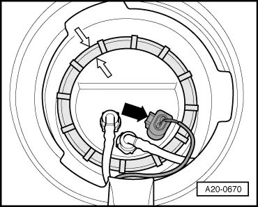
–  Unplug electrical connector -arrow- at flange.
  A20-0670
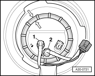
–  Mark fuel supply pipe -1- and fuel return pipe -2-.
  WARNING
t  In extreme cases the fuel lines and the fuel can reach a temperature of 100 °C on vehicles with unit injector engine. Allow the fuel to cool down before disconnecting the lines - danger of scalding.
t  Wear protective gloves.
t  Wear safety goggles.
–  Detach both pipes from flange (press release tabs).
Vehicles with supplementary heater:
–  Disconnect fuel pipe leading to metering pump for supplementary heater.
  A20-0721
All models:
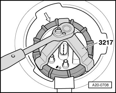
–  Use spanner for union nut -3217- to unscrew union nut.
–  Pull fuel gauge sender with fuel collector and seal out of opening in fuel tank.
  Note
t  When removing fuel collector, make sure you do not bend float arm of fuel gauge sender -G-.
t  Keep in mind that the fuel collector still contains fuel.
  Caution
First release retainer tabs on connector contact before detaching electrical connectors on fuel gauge sender -G-.
  A20-0708
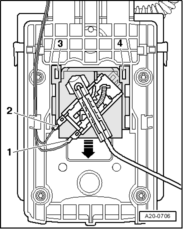
–  Release retainer tabs on electrical connectors -1- and -2- and then detach electrical connectors.
–  Lift retaining tabs -3- and -4- with a screwdriver and pull fuel gauge sender -G- off downwards -arrow-.
Installing
Installation is carried out in the reverse order; note the following:
  Note
t  Renew seal.
t  Take care not to bend the fuel gauge sender when fitting fuel collector.
–  Insert fuel gauge sender -G- into guides on fuel collector and press upwards until sender clicks into place.
–  Plug in electrical connectors and check that they have engaged properly.
  A20-0706
–  Make sure new seal for flange is installed dry.
–  Insert fuel collector in fuel tank.
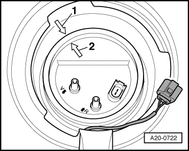
–  Press flange down against spring pressure, and turn flange to installation position.
l  Arrow -2- on flange must align with arrow -1- on fuel tank.
  A20-0722
–  Use union nut tool -3217- to tighten union nut.
  A20-0708
–  Connect fuel pipes.
l  Fit blue return pipe -2- onto connection marked “R”.
l  Fit black supply pipe -1- onto connection marked “V”.
Tightening torque
  A20-0721
ComponentNm
Union nut for fuel collector80


Servicing tandem pump > < Checking fuel gauge sender G