audi Workshop Repair Guides

Audi Workshop Service and Repair Manuals

Bleeding fuel system > < Checking rpm signal
MM-MPI injection and ignition system (4-cylinder)
Checking additional signals
Checking data bus

Notes:

  • ◆ The data exchange between the various control units is carried out via a data bus.
  • ◆ The term "CAN data bus" refers to a system for transmitting and distributing data.
  • ◆ The wires which connect the control units and convey the data between them are called data wires.
  • ◆ Data is transmitted via data wires in sequence, i.e. in a specific order to the connected control units (e.g. engine rpm and accelerator pedal position).

Testing bus system

The fault table indicates that the data exchange between the engine control unit, gearbox control unit, ABS/EDL control unit and airbag control unit or the dash panel insert should be tested.

  • ‒ Connect vehicle diagnostic, testing and information system VAS 5051 (or fault reader V.A.G 1551) and select engine electronics control unit by entering address word "01" ( .)
    When doing this the ignition must be switched on.
 
→ Indicated on display:
Rapid data transfer     HELP
Select function XX
  • ‒ Enter "08" to select the function "Read measured value block" and confirm entry with Q key.
 
→ Indicated on display:
Read measured value block    Q
Enter display group number XXX
  • ‒ Enter "125" for "Display group 125" and confirm with Q key.
  • ‒ Check display in display zones 1 ... 3.

Display zones

1

2

3

4

Display group 125: CAN bus

Display

---

---

---

Indicates

Anti-lock brake system

Gearbox

Dash panel insert ("Combi")

Airbag

Range

ABS 1
ABS 0

Gear. 0

Combi 1
Combi 0

Airbag 1
Airbag 0

Specification

ABS 1

Gear. 0

Combi 1

Airbag 1

  • ‒ Press C key.
 
→ Indicated on display:
Read measured value block    Q
Enter display group number XXX
  • ‒ Enter "126" for "Display group 126" and confirm with Q key.
  • ‒ Check display in display zone 3.

Display zones

1

2

3

4

Display group 126: CAN bus

Display

---

Indicates

Air conditioner

Range


Air cond.1
Air cond.0

Specification

Air cond.1

  • ‒ Press the ⇒key.

If a specification is not met:

  • ‒ Enter "06" to select the function "End output" and confirm entry with Q key.
 
→ When this display appears:
Rapid data transfer    HELP
Enter address word XX
  • ‒ Press key 0 twice for address word "Automatic test sequence" and confirm entry with Q key.
    • ‒ The fault memory of all on-board systems with self-diagnostic capability will be read.

When a control unit answers with its identification the number of stored faults appears on the display or "No fault recognised".

Any system faults that are stored will be displayed one after the other and printed out. The V.A.G 1551 will then transmit the next address word.

 
→ The automatic test sequence has ended when the following appears on the display:
V.A.G - SELF-DIAGNOSIS    HELP
1 - Rapid data transfer*
2 - Flash code output*

If faults have been stored relating to the "Drive train data bus" or to the "CAN data bus":

  • ‒ Check that the engine control unit, gearbox control unit, ABS/EDL control unit and airbag control unit or the dash panel insert are the correct versions for the vehicle (check Part No. and coding).

If the correct control units are installed:

  • ‒ Check that multi-pin connectors for control units are properly seated.

If the multi-pin connectors are properly seated:

  • ‒ Test CAN bus system.

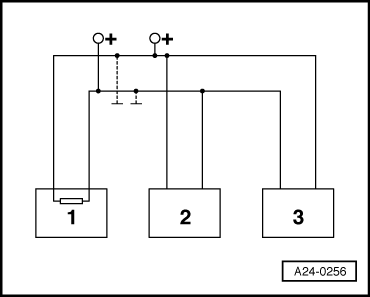
Testing a "two-wire bus system"

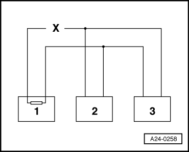
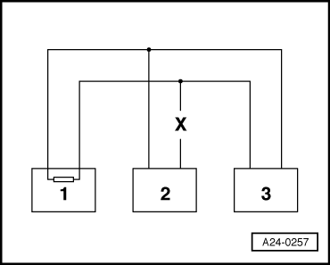
Three or more control units communicating via a "two-wire bus system"

  • ‒ Read out the faults stored in the control units.

Note:

This will help to trace a fault in the wiring.

Example 1:

From the faults present in the fault memories, you can see that control unit 1 has no connection to control units 2 or 3.

 
A24-0258

Control unit

Faults present in fault memory:

1

- No message from control unit 2
- No message from control unit 3

2

- No message from control unit 1

3

- No message from control unit 1

  • ‒ Switch off ignition.
  • ‒ Disconnect the control units which are linked by the bus wires and check whether there is an open circuit in one of the bus wires

=> Current flow diagrams, Electrical fault finding and Fitting locations

  • ‒ If no fault can be found in the bus wires replace control unit 1.

Example 2:

From the faults present in the fault memories, you can see that control unit 2 has no connection to control units 1 or 3.

 
A24-0257

Control unit

Faults present in fault memory:

1

- No message from control unit 2

2

- No message from control unit 1
- No message from control unit 3

3

- No message from control unit 2

  • ‒ Switch off ignition.
  • ‒ Disconnect the control units which are linked by the bus wires and check whether there is an open circuit in one of the bus wires

=> Current flow diagrams, Electrical fault finding and Fitting locations

  • ‒ If no fault can be found in the bus wires replace control unit 2.

Example 3:

From the faults present in the fault memories, you can see that none of the control units are able to transmit or receive signals.

Control unit

Faults present in fault memory:

1

- Data bus drive defective

2

- Data bus drive defective

3

- Data bus drive defective

  • ‒ Switch off ignition.
 
A24-0256
  • ‒ → Disconnect the control units which are linked by the bus wires and check for a short circuit to positive or earth in the bus wires

=> Current flow diagrams, Electrical fault finding and Fitting locations

If the cause of the fault "Data bus drive defective" cannot be found in the data bus wires, check whether one of the control units is causing the fault.

At this stage all the control units which communicate via the CAN data bus are disconnected. The ignition is switched off.

  • ‒ Connect one of the control units.
  • ‒ Connect fault reader V.A.G 1551. Switch on the ignition and erase the fault memory of the control unit which has just been connected. End output from fault reader with function 06 "End output".
  • ‒ Switch the ignition off and then on again.
  • ‒ Leave the ignition switched on for 10 seconds. Then interrogate the fault memory of the control unit that has just been connected, using the fault reader.
  • ‒ If the fault "Data bus drive defective" is now indicated, replace the control unit which has just been connected.
  • ‒ If the fault "Data bus drive defective" is not indicated, connect the next control unit, and repeat the above procedure.

Bleeding fuel system > < Checking rpm signal