audi Workshop Repair Guides

Audi Workshop Service and Repair Manuals

Checking rpm signal > < Checking signal from brake light switch and brake pedal switch
MM-MPI injection and ignition system (4-cylinder)
Checking additional signals
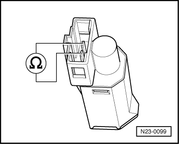
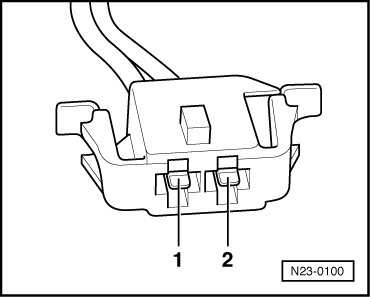
Testing clutch pedal switch -F36

Note:

This signal is used to avoid over-revving and load change jolts when disengaging the clutch. It is also needed for the cruise control system.

Test sequence

  • ‒ Connect the fault reader V.A.G 1551 (V.A.G 1552). Then switch ignition on and select engine control unit with the "Address word" 01.
    (Connecting fault reader and selecting engine control unit
    .)
 
→ Indicated on display:
Rapid data transfer    HELP
Select function XX
  • ‒ Press keys 0 and 8 for the function "Read measured value block" and confirm entry with Q key.
 
→ Indicated on display:
Read measured value block
Enter display group number XXX
  • ‒ Press keys 0, 0 and 6 for "Display group 6" and confirm with Q key.
 
→ Indicated on display:
Read measured value block 6    ⇒
    0 km/h    0    0    0    0.0 %    255
  • ‒ Observe display in display zone 2.
  • Specification: 0 0 0
  • ‒ Operate clutch pedal. The left-hand position must change to 1.
 
→ Indicated on display:
Read measured value block 6    ⇒
    0 km/h    1    0    0    0.0 %    255
  • Specification: 1 0 0

If the specifications are not obtained:

  • ‒ Press the ⇒key.
  • ‒ Press keys 0 and 6 for the "End output" function and confirm input with the Q key.
  • ‒ Switch off ignition.

If the specifications are not obtained:

Testing switches

 
N23-0099
  • ‒ Remove storage compartment (shelf) on driver's side.

=> General body repairs, Interior; Repair group 68; Storage compartments, covers; Removing driver's storage compartment

  • ‒ Unplug connector from clutch pedal switch.
  • ‒ → Connect multimeter to switch (resistance measurement range)
  • Specification: approx. 0 ω
  • ‒ Depress the clutch pedal.
  • Specification: ∞ ω (no continuity)

If the specifications are not obtained:

  • ‒ Renew clutch pedal switch.

=> Running gear, Front-wheel drive and four-wheel drive; Repair group 46

If the specifications are obtained:

Testing voltage supply

 
N23-0100
  • ‒ → Connect voltage tester V.A.G 1527 B as follows:

Connector
Contact

Measure against

1

Body earth

  • ‒ Switch on ignition.
  • Specification: the LED should light up.
  • ‒ Switch off ignition.

If the LED does not light up:

  • ‒ Test wiring for open circuits and rectify if necessary.

=> Current flow diagrams, Electrical fault finding and Fitting locations binder

If the LED lights up:

Testing wiring

  • ‒ Connect test box V.A.G 1598/31 to wiring harness for engine control unit. Do not connect to the engine control unit itself.
    => Page 24-8.
 
N23-0100
  • ‒ → Test for open circuit and short to positive or earth in the following wiring connections:

Connector
Contact

Test box V.A.G 1598/31
Socket

2

39

  • Resistance in wiring: max. 1.5 ω
  • ‒ Rectify short circuit or open circuit if necessary.

=> Current flow diagrams, Electrical fault finding and Fitting locations binder

If no fault is found:

  • ‒ Replace engine control unit
    => Page 24-125.

Checking rpm signal > < Checking signal from brake light switch and brake pedal switch