
A2
|
General notes on self-diagnosis
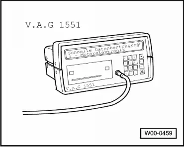
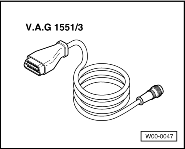
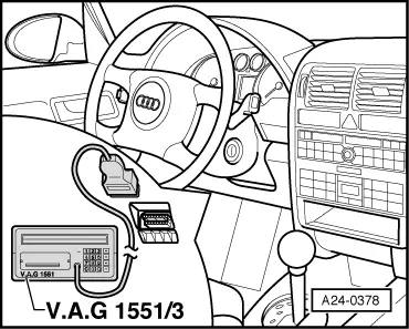
Connecting fault reader V.A.G 1551 and selecting engine electronicscontrol unit
|
 |
|
|
Special tools, workshop equipment, testers, measuring instruments and auxiliary items required
|
 |
|
Test conditions
|
 |
|
Work sequence
Warning:
Note: The following description only covers the procedure for performing self-diagnosis with fault reader V.A.G 1551. |
| → Indicated on display: |
|
|||
|
* Appears alternately
=> Current flow diagrams, Electrical fault finding and Fitting locations binder Depending on the function required:
|
| → Indicated on display: |
|
||
|
|
| → Press keys 0 and 1 for address word "Engine electronics" and confirm entry by pressing the Q key. |
|
||
| → If the display shows one of the messages reproduced here, check the diagnosis wiring. |
|
||
|
=> Current flow diagrams, Electrical fault finding and Fitting locations binder |
|
|||
|
|||
| → The display on fault reader V.A.G 1551 will show the control unit identification. For example: |
|
|||||||||||||||||
|
| → Indicated on display (chassis No. of vehicle) |
|
||
|
| → Indicated on display: |
|
||
|