audi Workshop Repair Guides

Audi Workshop Service and Repair Manuals

Measured value blocks (datablocks) > < Reading readiness code
MM-MPI injection and ignition system (4-cylinder)
Readiness code
Generating readiness code

Special tools, workshop equipment, testers, measuring instruments and auxiliary items required

  • ◆ Fault reader V.A.G 1551 (or vehicle system tester V.A.G 1552) with cable V.A.G 1551/3
 
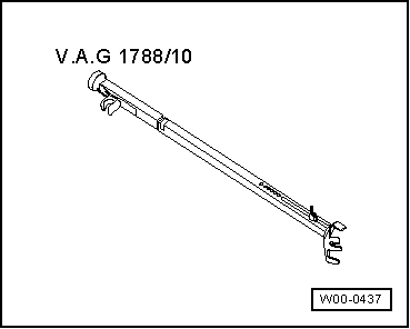
W00-0437
  • ◆ → V.A.G 1788/10 Engine speed adjuster

Test conditions

  • ● Vehicle stationary
  • ● On vehicles with automatic gearbox selector lever in "P" or "N" position
  • ● All electrical consumers, e.g. lights and rear window heating must be switched off.
  • ● Intake air temperature less than 60°C
    =>display group 04, display zone 4
  • ● Coolant temperature must be at least 80 °C, =>display group 04, display zone 3.

Work sequence

  • ‒ Connect fault reader V.A.G 1551 (V.A.G 1552). Start engine and select "Address word" 01 of engine control unit. When doing this the engine must be running at idling speed.
    (Connecting fault reader and selecting engine control unit
    .)

Work step 1: Interrogate fault memory

 
→ Indicated on display:
Rapid data transfer    HELP
Select function XX
  • ‒ Press keys 0 and 2 for function "Interrogate fault memory" and confirm entry with Q key.
 
→ The number of faults stored or "No fault recognised!" will be shown on the display.
X Faults recognised!

If a fault is stored:

  • ‒ Rectify faults printed out using fault table:
    SAE P0 codes=> Page 01-41

If no fault is stored:

  • ‒ Press ⇒key.

Work step 2: Erase fault memory

 
→ Indicated on display:
Rapid data transfer    HELP
Select function XX
  • ‒ Press keys 0 and 5 for the function "Erase fault memory" and confirm entry with Q key.

Note:

The readiness code is reset or erased each time fault memory is erased.

 
→ Indicated on display:
Rapid data transfer    ⇒
Fault memory is erased!

Note:

If the ignition is switched off between "Interrogate fault memory" and "Erase fault memory" the fault memory will not be erased.

  • ‒ Press ⇒key.

Note:

  • ◆ During the work sequence the engine must not be switched off.

Work step 3: Activated charcoal filter system diagnosis (tank breathing system)

 
→ Indicated on display:
Rapid data transfer    HELP
Select function XX
  • ‒ Press keys 0 and 4 for the "Introduce basic setting" function and confirm entry with Q key.
 
→ Indicated on display:
Basic setting
Input display group number XXX
  • ‒ Press keys 0, 7 and 0 for "Display group number 70" and confirm entry with Q key.
 
→ Indicated on display:
(1...4 = Display zones)
System in basic setting    70    ⇒
    1    2    3    4    

Note:

Do not press clutch pedal or brake pedal.

When the diagnosis is initiated by the engine control unit the display in display zone 4 jumps from "Test OFF" to "Test ON"

  • ‒ Run engine at idling speed until the
        specification "TVV OK"
    is displayed in display zone 4.

If the display does not indicate as described:

  • ‒ Interrogate fault memory => Page 01-19.
  • ‒ Generate about 3 throttle bursts and repeat the diagnosis.

If the display indicates as described:

  • ‒ Press C key.

Work step 4: Lambda probe ageing diagnosis (cycle duration monitor)

 
→ Indicated on display:
Basic setting
Input display group number XXX
  • ‒ Press keys 0, 3 and 4 for "Display group number 34" and confirm entry with Q key.
 
→ Indicated on display:
(1...4 = Display zones)
System in basic setting    34    ⇒
    1    2    3    4    
  • ‒ Rev up engine twice to over 5,000 rpm.
  • ‒ Set engine speed to 1500...3900 rpm using speed regulator V.A.G 1788/10:
  • ‒ Maintain the engine speed until the display
        in display zone 4 jumps from "Test OFF" to "Test ON".
  • ‒ Continue to maintain the same speed until
        specification "B1-P1 OK"
    appears in display zone 4.
  • ‒ Press ⇒key.
 
→ Indicated on display:
Rapid data transfer    HELP
Select function XX
  • ‒ Press keys 0 and 8 for the function "Read measured value block" and confirm entry with Q key.
 
→ Indicated on display:
Read measured value block
Input display group number XXX
  • ‒ Press keys 0, 3 and 0 for the "Display group number 30" and confirm entry with Q key.
 
→ Indicated on display:
(1...4 = Display zones)
Read measured value block    30    ⇒
    1    2    3    4    
  • ‒ Check the operating condition of the lambda control in front of catalytic converter (display zone 1):
        Specification: 111
  • ‒ Check the operating condition of the lambda control after catalytic converter (display zone 2):
        Specification: 110

Note:

The 3rd bit in display zone 2 (i.e. Lambda regulation active) will not be set to 1 until the part-throttle condition (2500-4000 rpm) is reached.

Significance of 3 digit number block in display zones 1 and 2:

Significance if display = 1

1

2

3

1

Lambda control active (partial throttle)

1

Lambda probe operationally ready

1

Lambda probe heating on

If the specifications are not obtained:

  • ‒ Interrogate fault memory => Page 01-19.

If the specifications are obtained:

  • ‒ Press ⇒key.

Work step 5: Catalytic converter diagnosis

Note:

This diagnosis is terminated only when there are no faults in the Lambda probe and activated charcoal filter systems.

 
→ Indicated on display:
Rapid data transfer    HELP
Select function XX
  • ‒ Press keys 0 and 4 for the function "Initiating basic settings" and confirm entry with Q key.
 
→ Indicated on display:
Basic setting
Input display group number XXX
  • ‒ Press keys 0, 4 and 6 for "Display group number 46" and confirm entry with Q key.
 
→ Indicated on display:
(1...4 = Display zones)
System in basic setting    46    ⇒
    1    2    3    4    
  • ‒ Maintain engine speed at 1500...3900 rpm until display in
        display zone 4 jumps from "Test OFF" to "Test ON".
    Catalytic converter temperature in
        display zone 2 must be at least 300 °C.
  • ‒ Continue to maintain engine speed at 1500...3900 rpm until
        Specification "Cat B1 OK" appears in
        display zone 4.

Note:

It can take several minutes for the display to change from "Test ON" to "Cat B1 OK".

If the specifications are not attained:

  • ‒ Interrogate fault memory => Page 01-19.

If the specification is obtained:

  • ‒ Press C key.

Work step 6: Exhaust gas recirculation system diagnosis

 
→ Indicated on display:
Basic setting
Input display group number XXX
  • ‒ Press keys 0, 7 and 5 for the "Display group number 75" and confirm entry with Q key.
 
→ Indicated on display:
(1...4 = Display zones)
System in basic setting    75    ⇒
    1    2    3    4    

Note:

Do not press clutch pedal or brake pedal.

  • ‒ Rev. up briefly maximum engine speed approx. 5 times.

If the diagnosis is initiated from engine control unit the display in display zone 4 jumps from "Test OFF" to "Test ON"

  • ‒ Leave the engine running at idle until
        specification "Sys. OK"
    appears in display zone 4.

If the display does not indicate as described:

  • ‒ Interrogate fault memory => Page 01-19.

If the display indicates as described:

  • ‒ Press ⇒key.
  • ‒ Press keys 0 and 6 for the "End output" function and confirm input with the Q key.
  • ‒ Read readiness code => Page 01-84

Measured value blocks (datablocks) > < Reading readiness code