audi Workshop Repair Guides

Audi Workshop Service and Repair Manuals

Removing and installing injection system components > < Technical data
Motronic Direct Injection and Ignition System (4-Cyl.)
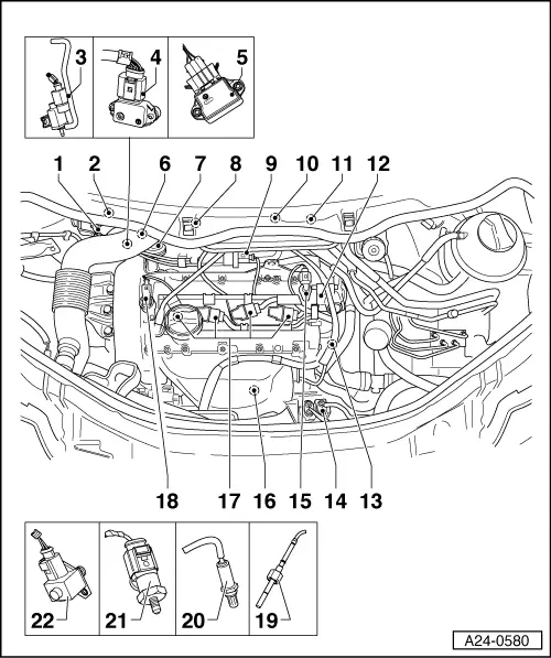
Servicing Motronic injection system
Exploded view of fitting locations

Components A to G are not shown in the exploded view.

  •     A -    Brake light switch -F and brake pedal switch -F47
    • ◆ In footwell at pedal bracket next to brake pedal
  •     B -    Diagnostic connector
    • ◆ In driver's knee restraint
  •     C -    Fuel pump relay -J17
    • ◆ 6+6-socket relay carrier (left side footwell, relay position 5) =>Fig. 24-13
  •     D -    Motronic current supply relay -J271
    • ◆ 3-socket relay carrier (left side footwell, relay position 1) =>Fig. 24-14
 
A24-0580
  •     E -    Motronic control unit -J220
    • ◆ Fitting location =>Fig. 24-13
  •     F -    NOx sender control unit -J583
    • ◆ Fitting location =>Fig. 24-13
  •     G -    Accelerator position sender -G79 and accelerator pedal position sender 2 -G185
    • ◆ In footwell at accelerator pedal (both senders share same housing)
  • Fuel pressure regulator
    • ◆ Fitting location =>Fig. 24-10
  • Fuel metering valve -N290
    • ◆ Fitting location =>Fig. 24-10
 
A24-0580
  • Intake manifold flap air flow control valve -N316
    • ◆ Fitting location =>Fig. 24-10
  • Intake manifold pressure sender
    -G71
    • ◆ Fitting location =>Fig. 24-10
  • Intake manifold flap potentiometer
    -G336
    • ◆ Fitting location =>Fig. 24-10
  • Engine speed sender -G28
  • Vacuum actuator
  • Air-mass meter -G70 with intake-air temperature sender -G42
 
A24-0580
  • Activated charcoal filter system solenoid valve 1 -N80
  • Throttle valve control unit -J338
  • Exhaust-gas recirculation valve -N18 with exhaust-gas recirculation potentiometer -G212
  • High-pressure fuel pump
  • Coolant temperature sender -G62
  • Fan control unit
  • Hall sender -G40
  • Lambda probe -G39, -Z19
    • ◆ Fitting location =>Fig. 24-11
 
A24-0580
  • Ignition coils with output stages
  • Camshaft adjustment valve 1 -N205
  • Exhaust-gas temperature sender 1 -G235
    • ◆ Fitting location =>Fig. 24-11
  • NOx sender -G295
    • ◆ Fitting location =>Fig. 24-12
  • Fuel-pressure sender -G247
    • ◆ Fitting location =>Fig. 24-12
  • Fuel-pressure regulating valve -N276
    • ◆ Fitting location =>Fig. 24-12
 
A24-0564

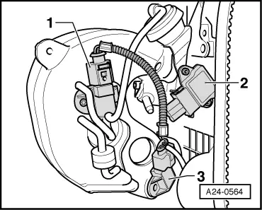
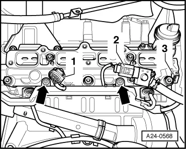
→ Fig.1

1- Intake manifold flap air flow control valve -N316

2- Intake manifold flap potentiometer -G336

3- Intake manifold pressure sender -G71

 
A24-0585

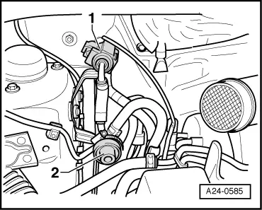
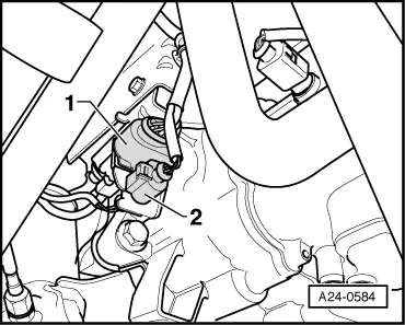
→ Fig.2

1- Fuel metering valve -N290

2- Fuel pressure regulator

 
A24-0582

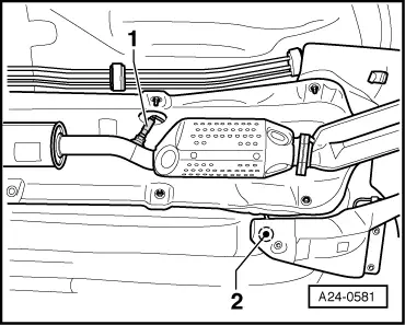
→ Fig.3

1- Lambda probe -G39, -Z19

2- Exhaust-gas temperature sender 1 -G235

 
A24-0584

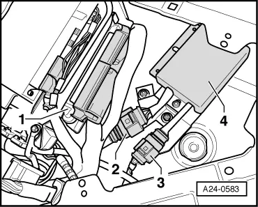
→ Fig.4

1- Connector coupling for lambda probe

2- Connector coupling for exhaust-gas temperature sender

 
A24-0581

→ Fig.5

1- NOx sender -G295

2- Cable duct into passenger compartment

 
A24-0568

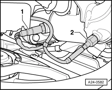
→ Fig.6    Lower part of intake manifold

1- Fuel-pressure sender -G247

2- Fuel-pressure regulating valve -N276

 
A24-0583

→ Fig.7

1- Motronic control unit -J220

2- From NOx sender -G295

3- To engine control unit

4- Control unit for NOx sender -G583

 
A97-0219

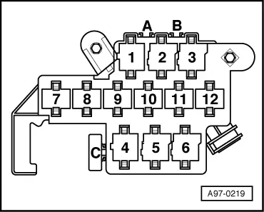
→ Fig.8    6+6-socket relay carrier (in left side footwell)

Relay position 5- Fuel pump relay -J17

 
A97-0215

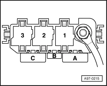
→ Fig.9    3-socket relay carrier (in left side footwell)

Relay position 1- Motronic current supply relay -J271

Removing and installing injection system components > < Technical data