
A2
 |
|
|
 |
|
|
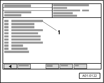
→ Readout on VAS 5051:
|
 |
|
|
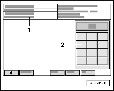
→ Readout on VAS 5051:
|
 |
|
|
→ Readout on VAS 5051:
|
 |
|
→ Readout on VAS 5051:
|
 |
|
|
→ Readout on VAS 5051:
|
 |
|
|
→ Readout on VAS 5051:
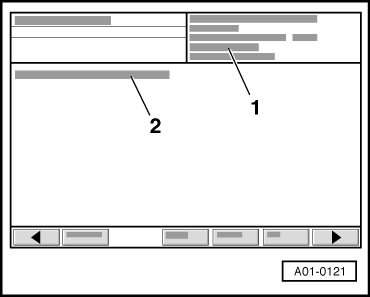
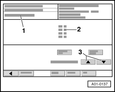
Watch the readout in display zone 3. When the engine is idling, a value from 60 to 70 bar is shown in display zone 3. The readout shows the current pressure (actual pressure) in the fuel rail which is being generated by the high-pressure pump. In display zone 2, the predefined pressure is displayed by the engine control unit (specification). The values for specification and actual value should be identical. |
 |
|
Note: The readout must not fall below 5 bar, otherwise the engine will stall (this could damage the catalytic converter). The readout in display zone 3 decreases (process takes between 2 and 3 minutes) because the mechanical high-pressure pump is no longer being supplied with fuel from the fuel tank by the electric fuel pump.
The fuel rail is still full of fuel; the fuel is, however, no longer under high pressure. Components or lines can now be opened. A clean cloth must be wrapped around the joints. Any discharged fuel must be collected.
|