audi Workshop Repair Guides

Audi Workshop Service and Repair Manuals

Fault messages in CAN bus system > < Function of CAN bus
Running gear self-diagnosis for ESP, steering
CAN bus
Testing "two-wire bus system"

If fault table indicates that bus should be checked:

  • ‒ Use appropriate current flow diagram to establish how many control units are linked to CAN bus.
  • ‒ Check for proper connection of multi-pin connectors of control units.
  • ‒ Connect up one of the fault readers V.A.G 1551/1552 or VAS 5051 and press key 0 twice for "Automatic test sequence" function.
  • Before examining bus wires, make sure there are no malfunctions in any of the control units connected to the bus.

The term "malfunction" refers to a fault which does not directly affect the bus system but does somehow impair the operating sequence of a system. This may for example be a defective sensor. As a result, the sensor signal can no longer be conditioned for bus system data transfer. Such a malfunction has an indirect effect on the bus system. Problems will be encountered with communication with the other control units requiring the sensor signal concerned.

Is there a malfunction?

  • Start by rectifying this.
  • ‒ Note down faults and erase fault memories of all control units .
  • ‒ Press keys 0 and 6 for "End output" function and confirm entry with Q key.
  • ‒ Conclude fault reader output with "End output" function => Page 01-16.
  • ‒ Repair malfunctions using fault table in appropriate Workshop Manuals.

After rectifying all malfunctions:

  • ‒ Examine bus wires if there are still problems with control unit communication.

A distinction must be made between two situations when performing bus wire fault-finding:

  • ◆ Two control units communicating by way of a "two-wire bus system"
  • ◆ Three or more control units communicating by way of a "two-wire bus system"

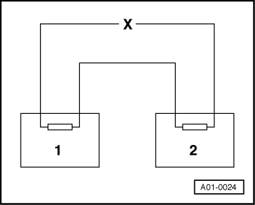
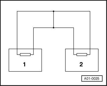
Communication between two control units by way of a "two-wire bus system"

 
A01-0024
  • ‒ Switch off ignition.
  • ‒ → Unplug the two control units.
  • ‒ Check for open circuit in one of the bus wires.

=> Current Flow Diagrams, Electrical Fault-finding and Fitting Locations binder

 
A01-0025
  • ‒ → Check for mutual short circuit in bus wires.

=> Current Flow Diagrams, Electrical Fault-finding and Fitting Locations binder

 
A01-0026
  • ‒ → Check for short to positive/earth in one of the bus wires.

If no faults are found in bus wires:

  • ‒ Try replacing the control unit which is quickest and least expensive to exchange.
  • ‒ Replace second control unit if there are still problems with control unit communication via bus.

Fault messages in CAN bus system > < Function of CAN bus