
A2
 Note
Note
|
|
|
|
|
|
|
|
|
|
|
|
|
|
|
|
|
|
|
|
|
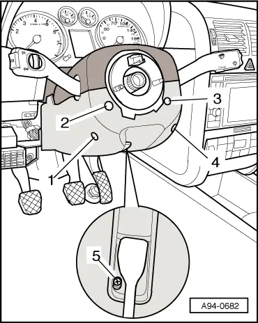
| Component | Nm |
| Steering column switch to an steering column | 3 |
| Trim for steering column switch | 1 |