
A2
| Vehicles with 1.4 l MPI engine |
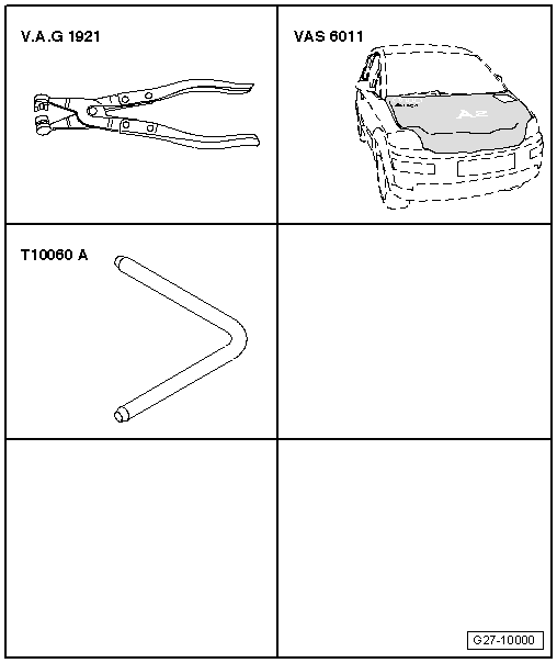
| Special tools and workshop equipment required |
| t | Hose clamp fitting tool -V.A.G 1921- |
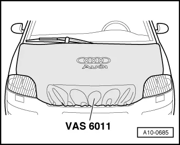
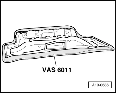
| t | Protective cover for bonnet Audi A2 -VAS 6011- |
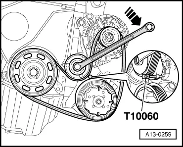
| t | Locking pin -T10060 A- |
 Note
Note
|
 Caution
|
|
Note |
|
|
|
|
|
Note |
|
|
|
|
|
|
|
Note
Note
|
|
|
|
| Component | Nm |
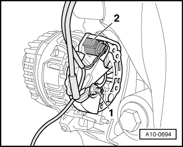
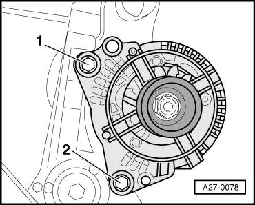
| Alternator to bracket | 25 |
| Terminal 30/B+ wire to alternator | 16 |
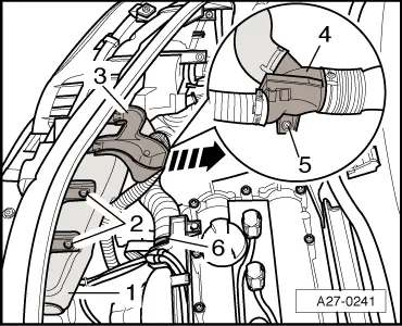
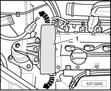
| Intake air preheater to lock carrier | 3.5 |
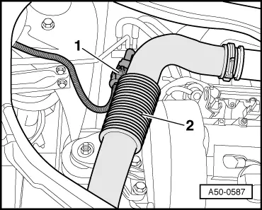
| Air hose to lock carrier | 2.5 |