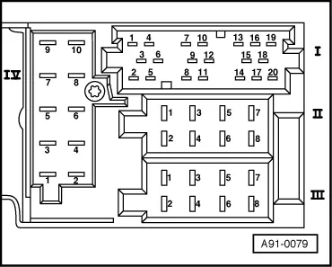
audi Workshop Repair Guides

Audi Workshop Service and Repair Manuals

Connectors at “concert” radio > < Connectors at “chorus” radio
Contact assignment of multi-pin connectors
  Note!
Contacts not listed are not used.
   
20-pin connector I
7 - CAN bus High (infotainment)
8 - Clock signal (up to MY 01)
9 - Data signal (up to MY 01)
10 - Enable signal (up to MY 01)
12 - CAN bus Low (infotainment)
  A91-0079
Brown 8-pin connector II
1 - Rear right loudspeaker (+)
2 - Rear right loudspeaker (-)
3 - Front right loudspeaker (+)
4 - Front right loudspeaker (-)
5 - Front left loudspeaker (+)
6 - Front left loudspeaker (-)
7 - Rear left loudspeaker (+)
8 - Rear left loudspeaker (-)
Black 8-pin connector III
1 - GALA (vehicle speed signal) (up to MY 01)
2 - Telephone muting (up to MY 01)
 - Anti-theft alarm earth (as of MY 02)
3 - K-diagnosis
4 - Terminal 86s (up to MY 01)
6 - Terminal 58s (up to MY 01)
7 - Terminal 30
8 - Terminal 31
  A91-0079
Red 10-pin connector IV
1 - AF mute (from telephone)
2 - Terminal 15 (navigation system only) (up to MY 01)
3 - Telephone (AF +) (not with navigation system)
4 - Telephone (AF -) (not with navigation system)
5 - Navigation (AF+) (navigation system only)
6 - Navigation (AF-) (navigation system only)
7 - Navigation (control wire) (navigation system only)
9 - Terminal 58d (up to MY 01)
  A91-0079

Connectors at “concert” radio > < Connectors at “chorus” radio