audi Workshop Repair Guides

Audi Workshop Service and Repair Manuals

Removing and installing head airbag - 5-door vehicles > < Repairing head airbag
General Body Assembly, Interior (Repair groups 68, 69, 70, 72, 74)
Repairing head airbag
Removing and installing head airbag - 3-door vehicles
Important=>
  • Head airbag
  • ◆ Removing
    • ‒ Remove upper A-pillar trim
    • ‒ Remove upper B-pillar trim without removing seat belt => Page 70-113
    • ‒ Remove upper D-pillar trim => Page 70-118
    • ‒ Remove headlining => Page 70-72
 
A69-0206
    • ‒ Remove bolts -3- (2x).
    • ‒ Fold front part of head airbag backwards and attach to Velcro fastening (magnified view).
    • ‒ Unplug connector -6- for head airbag at 4-pin connector between gas generator and roof => Fig.2
    • ‒ Unscrew bolt-4-.
    • ‒ Remove bolts -8- (2x).
    • ‒ Remove gas generator with locating pin -7- => Fig.4
    • ‒ Remove head airbag -1- at grab handles -2-.
Important
Always observe installation sequence of head airbag
 
A69-0206
  • ◆ Installing
    • ‒ Before installing the head airbag module, check the contact surface for the head airbag at the threaded bushings on the roof grab handle => Fig.6
    • ‒ Check clamp mounts for B-pillar trim before installing B-pillar trim => Fig.7
    • ‒ Secure head airbag with pre-retainer clips at grab handle adapters -2- (2x) => Fig.5
    • ‒ Secure gas generator with roof frame locating pin -7- => Fig.4
    • ‒ Insert bolts -8- (2x), pressing airbag module -1- with one hand at rear roof grab handle bolting point => Fig.1
 
A69-0206
    • ‒ Detach front part of head airbag -1- and fold towards A-pillar; while doing this anti-twist seam -A- must point in direction of centre of vehicle.
    • ‒ Insert bolt -3- => Fig.3
    • ‒ Remainder of installation is carried out in reverse order of removal.
    • ‒ Switch ignition on.
Important
There must be no-one in the vehicle when the battery is being connected.
    • ‒ Connect battery.
  • Grab handle adapter
 
A69-0206
  • Bolts (2x)
    • ‒ Tightening torque 4 Nm
    • ◆ Self-locking
    • ◆ Replace
    • ◆ Threaded bores for bolts must always be cleaned (e.g. with a thread tap).
    • ◆ If threaded bushings are loose, re-tighten using riveting pliers.
  • Bolt
    • ‒ Tightening torque 4 Nm
    • ◆ Self-locking
    • ◆ Replace
    • ◆ Threaded bores for bolts must always be cleaned (e.g. with a thread tap).
    • ◆ If threaded bushings are loose, re-tighten using riveting pliers.
 
A69-0206
  • Gas generator
  • Connector for head airbag
  • Locating pin
  • Bolts (2x)
    • ‒ Tightening torque 4 Nm
    • ◆ Self-locking
    • ◆ Replace
    • ◆ Threaded bores for bolts must always be cleaned (e.g. with a thread tap).
    • ◆ If threaded bushings are loose, re-tighten using riveting pliers.
 
A69-0204

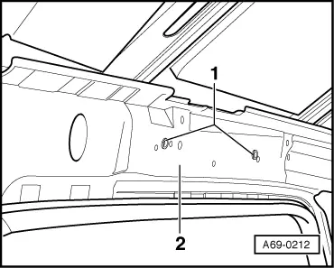
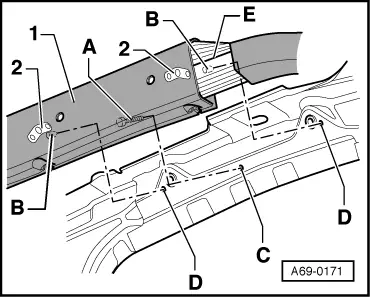
Fig.1    Gas generator to roof frame

  • ‒ Screw in bolts -8-.
  • ‒ Tightening torque 4 Nm
  • ‒ Screw in bolt -4-.
  • ‒ Tightening torque 4 Nm
  •     1 -    Head airbag
  •     5 -    Gas generator
  •     6 -    Airbag connector

 
A69-0177

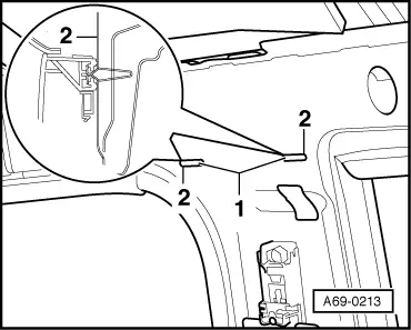
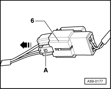
Fig.2    Detaching connector for head airbag

  • ‒ → Press release -A- and unplug connector in direction of arrow.
  •     6 -    Connector for head airbag
 
A69-0207

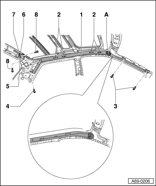
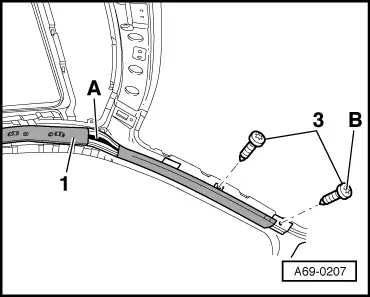
Fig.3    Head airbag to lower A-pillar

  • ‒ → First install lower bolts -B-.
  • ‒ Tightening torque 4 Nm
  •     1 -    Head airbag
  •     3 -    Bolts (2x)
  •     A -    Anti-twist seam

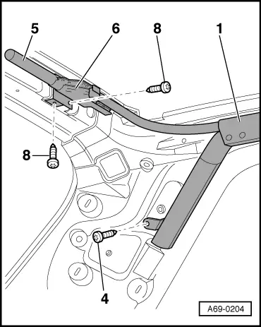
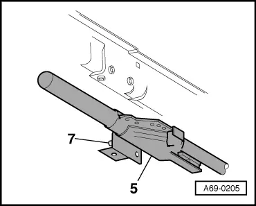
Fig.4    Gas generator bracket

 
A69-0205
  • ‒ → Remove gas generator -5- with locating pin -7-.

Fig.5    Securing head airbag at roof grab handle

 
A69-0171
  • ◆ Attachment of roof grab handle is the same at front and rear.
  • ‒ → Insert pre-retainer clip -A- into mounting -C-.
  • ‒ Insert pins -B- into mounting -D-.
  • ‒ Anti-twist seam -E- must face into direction of vehicle centre.
  •     1 -    Head airbag
  •     2 -    Adapter for grab handle
 
A69-0212

Fig.6    Checking contact surface for head airbag

  • ‒ Before installing any airbag, the sheet metal -2- in the threaded bushing area -1- (4 on each side) must be checked for deformation at the vehicle centre.
  • ◆ Illustration shows a contact surface which is OK.
  • ‒ Align sheet metal if necessary.
 
A69-0213

Fig.7    Checking clamp mounts for B-pillar trim

  • ‒ Before installing any trim, the sheet metal -2- in the area of the clamp mounts -1- (2 on each side) must be checked.
  • ◆ The sheet metal must lie flat on the mounts.
  • ◆ Illustration shows a clamp mount which is OK.
  • ‒ Align sheet metal if necessary.

Notes:

  • ◆ After connecting the battery, please ensure that the vehicle accessories (radio, clock, electric window lifters) are checked according to workshop manual and/or operating instructions.
  • ◆ If the fault warning light (K 75) for airbag signals a fault after assembly the fault memory must be erased and again be interrogated by using fault reader V.A.G 1551.

=> Body Self-diagnosis; Repair group 01

Removing and installing head airbag - 5-door vehicles > < Repairing head airbag