audi Workshop Repair Guides

Audi Workshop Service and Repair Manuals

Removing and installing operating and display unit -E87 > < Connection diagram for vacuum hoses for actuating the refrigerant shut-off valve
Heating, Air Conditioner
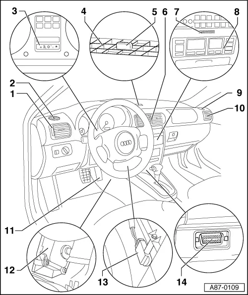
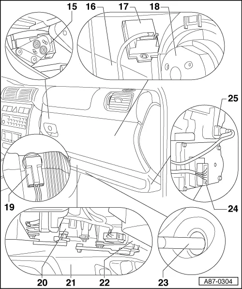
Components for air conditioner control and regulation (in the passenger compartment)
 
A87-0109

Notes:

  • ◆ After completing repair work, always interrogate and erase fault memory, perform basic setting, and check the -E87 encoding.
  • ◆ Check refrigeration capacity .
  • ◆ Refrigerant circuit .
  • ◆ All components marked with * are actuated during the final control diagnosis .
  • ◆ An electrical check can be performed on all components marked with ** .
  • ◆ Vents and air ductsof the dash panel.
 
A87-0109
  • ◆ Removing and installing dash panel fascia.

=> General body repairs,Interior; Repair group 70

  • Dash panel vent, left
    • ◆ Removing and installing .
  • Defroster vent for "side window"
    • ◆ Removing and installing.

=> Inner Body Assembly; Repair group 70

  • Ambient temperature indicator
    -G106 *
    • ◆ The ambient temperature determined can be displayed on the -E87 in °C or °F according to the respective setting.
 
A87-0109

Note:

In the event of a faulty display, check values measured by temperature sensor (Reading measured value block).

  • Windscreen defroster vent
    • ◆ Removing and installing .
  • Sunlight penetration photosensor
    -G107 **
    • ◆ Removing and installing .
  • Centre dash panel vent
    • ◆ Removing and installing .
  • Dash panel temperature sensor
    -G56 **
    • ◆ Removing and installing => Page 87-82.
 
A87-0109
  • Operating and display unit -E87.
    • ◆ Removing and installing => Page 87-65.
    • ◆ Different versions => Page 87-65.

Notes:

  • ◆ The display zone and operating controls are illuminated via LED's (not replaceable individually).
  • ◆ Different versions vary according to the production date and the vehicle version (e.g. vehicles with map-controlled cooling).

=> Parts List

  • ◆ Up to and including model year 2000 operating and display units -E87 with two displays were installed. As of model year 2001 the -E87 with one display is installed.
 
A87-0109
  • Defroster vent for "side window"
    • ◆ Removing and installing.

=> Inner Body Assembly; Repair group 70

  • Dash panel vent, right
    • ◆ Removing and installing .
  • Kickdown switch
    • ◆ The magnetic clutch is switched off following acceleration either by the engine control unit or the control unit for automatic transmission, depending on the vehicle equipment and the current vehicle speed (Reading measured value block).
 
A87-0109
  • Footwell/defroster flap positioning motor -V85 *
    • ◆ With potentiometer -G114
    • ◆ Removing and installing .
    • ◆ "yellow" pivot arm
  • Footwell vent temperature sender
    -G192 **
    • ◆ Removing and installing .
  • Connector for fault reader V.A.G 1551
    • ◆ Connect V.A.G 1551 and check air conditioner .
 
A87-0304
  • Temperature sensor blower -V42
    • ◆ Removing and installing => Page 87-83.
  • Air conditioner with evaporator
    • ◆ Removing and installing => Page 87-119.
    • ◆ Dismantle and assemble design "1" .
    • ◆ Dismantle and assemble design "2" .
Warning!
The air conditioner may be removed only if the refrigerant circuit is empty.
 
A87-0304

Note:

As of June 1997, AC version "1" has been gradually phased out of production and AC version "2" gradually phased in.

=> Parts List

  • Blower control unit -J126 **
    • ◆ Removing and installing .
  • Fresh air blower -V2 **
    • ◆ Removing and installing => Page 87-76.
  • Centre vent temperature sender
    -G191 **
    • ◆ Removing and installing => Page 87-74.
 
A87-0304

Note:

The sender for centre vent temperature -G191 is only present in vehicles with map-controlled engine cooling (at the moment only with 1.6 litre engine with gradual introduction into model year 1999).

=> Relevant Workshop Manual Injection and Ignition system

  • Positioning motor for central flap
    -V70 *
    • ◆ With potentiometer -G112
    • ◆ Removing and installing .
    • ◆ "Green" pivot arm
  • Footwell vent
    • ◆ Removing and installing => Page 87-78.
 
A87-0304
  • Temperature flap positioning motor
    -V68 *
    • ◆ With potentiometer -G92
    • ◆ Removing and installing .
    • ◆ "Black" or "pink" pivot arm
  • Condensation drain
    • ◆ Checking .
  • Air flow flap positioning motor -V71*
    • ◆ Actuates the air flow flap and fresh/recirculated air flap
    • ◆ With potentiometer -G113
    • ◆ Removing and installing .
  • Fresh air intake temperature sensor
    -G89 **
    • ◆ Removing and installing .

Removing and installing operating and display unit -E87 > < Connection diagram for vacuum hoses for actuating the refrigerant shut-off valve