audi Workshop Repair Guides

Audi Workshop Service and Repair Manuals

Electrical check of rear window heating > < Electrical check at control unit -J293 (version for High-pressure sensor -G65)
Heating, Air Conditioner
Perform electrical check at radiator fan control unit -J293
Check signal from high-pressure sensor -G65
 
A87-0340

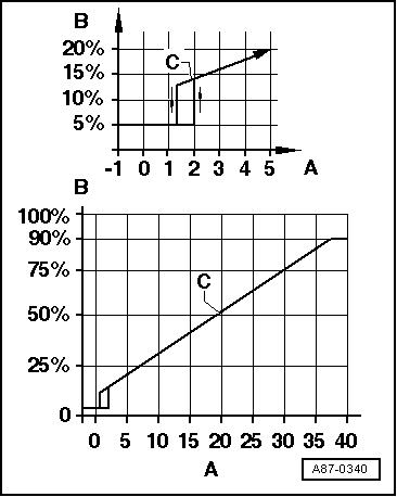
→ A- Pressure on high-pressure side of refrigerant circuit in bar (overpressure)

B- Duty cycle of the square-wave signal

C- Curve

Notes:

  • ◆ Control unit -J293 transmits a positive signal to operating and display unit -E87:
    • ‒ When duty cycle is larger than 13% (equivalent to approx. 1.2 bar overpressure) and less than 78% (equivalent to approx. 32 bar overpressure).
    • ‒ If the duty cycle is less than 13% or greater than 78%, no positive signal is transmitted to -E87, and -E87 transmits no signal to -J293 - as a result -J293 does not switch on the compressor (via magnetic clutch -N25).
  • ◆ If the refrigerant circuit pressure was greater than 32 bar (duty cycle greater than 78%), control unit -J293 does not re-transmits a positive signal to -E87 until the pressure drops below 24 bar (duty cycle less than 65%).
 
A87-0340
  • ◆ → Control unit -J293 switches radiator fan -V7 to speed 2:
    • ‒ As soon as the refrigerant circuit pressure exceeds 16 bar (duty cycle exceeds 45%). If the pressure drops below 12.5 bar (duty cycle drops below 37%), the fans are switched back to 1st speed.
    • ‒ Refrigerant thermoswitch -F18 closed.
    • ‒ As soon as a positive signal from the engine control unit is present (only in vehicles with map-controlled engine cooling).
  • ◆ The control unit -J293 switches radiator fans -V7 to 1. speed:
    • ‒ As soon as a signal from the -E87 for switching on of the compressor is present.
    • ‒ When thermo switch -F54 is closed.
    • ‒ As soon as a positive signal from the engine control unit is present (only in vehicles with map-controlled engine cooling and in vehicles with 81 KW diesel engine).
  • ◆ The signal generated by high-pressure sensor -G65 is also used for engine control (the required compressor drive torque is governed by the refrigerant circuit pressure). Depending on the engine control unit version, the signal in the measured value block is displayed as duty cycle.

=> Relevant Workshop Manual Injection and Ignition system

Check signal from -G65

 
A87-0260
  • ‒ → Connect test lead of one oscilloscope to the signal wire of high-pressure sensor -G65 ( test step 4).

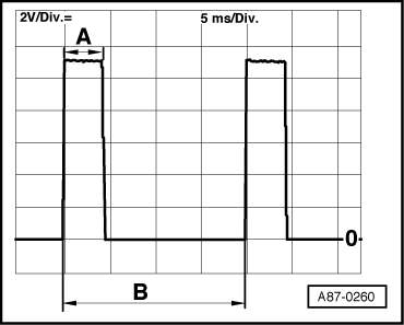
This display appears on the oscilloscope screen if the following conditions have been satisfied.

    • ‒ Ignition switched on (positive and earth applied at sender -G65)
    • ‒ Oscilloscope setting:
      2 V/Div. = (2 V DC per unit)
      5 ms/Div. (5 milliseconds per unit)
    • ‒ Test lead (signal wire) at contact 2 of high-pressure sensor -G65.
    • ‒ Test lead (screening) connected to earth.

Notes:

  • ◆ The illustration shows the signal transmitted at a refrigerant circuit pressure of approx. 5 bar overpressure, which is equivalent to a duty cycle of approx. 20% (automatic adjustment with compressor at a standstill, at an ambient temperature of 20 °C, and with filled refrigerant circuit).
 
A87-0260
  • ◆ → Pulse width -A- depends on the refrigerant circuit pressure (if the pressure increases, the -A- range widens).
  • ◆ Signal gap -B- is always 20 milliseconds.
  • ◆ The duty cycle is derived from the ratio between pulse width -A- and signal gap -B-.

Electrical check of rear window heating > < Electrical check at control unit -J293 (version for High-pressure sensor -G65)