
A3 Mk1
|

| Special tools and workshop equipment required |
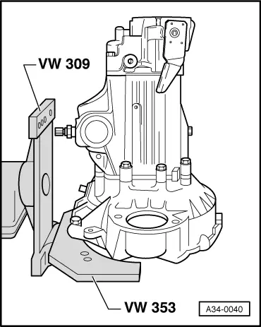
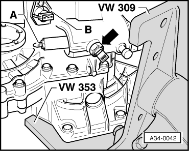
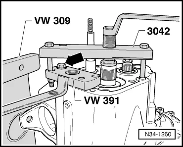
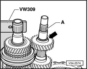
| t | Support plate -VW 309- |
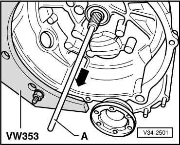
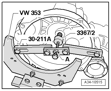
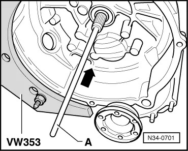
| t | Gearbox support -VW 353- |
| t | Support bridge -30 - 211 A- |
| t | Fitting tool -3367/2- |
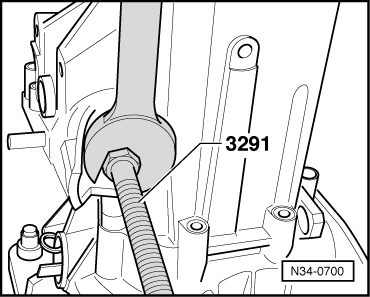
| t | Spindle -3291- |
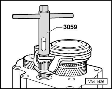
| t | Box wrench -3059- |

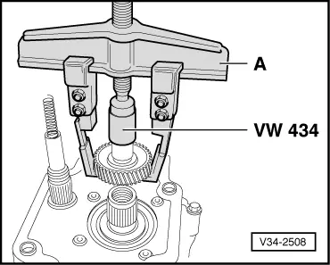
| t | Press tool -VW 434- |
| t | Puller -3042- |
| t | Thrust piece -3002- |
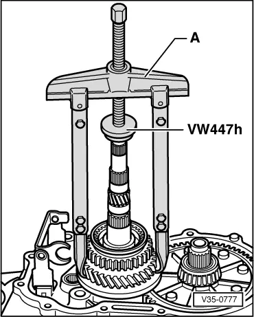
| t | Thrust plate -VW 447 H- |
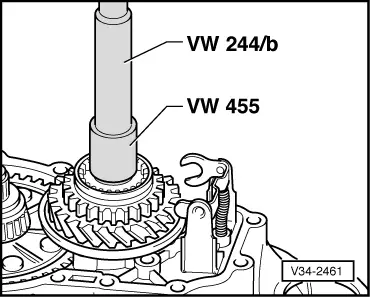
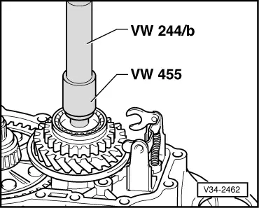
| t | Drift sleeve -VW 244 B- |
| t | Installing sleeve -VW 455- |

| t | Drive flange installing tool -VW 391- |
| t | Extension -30 - 23- |
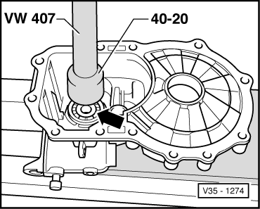
| t | Drift sleeve -40 - 20- |
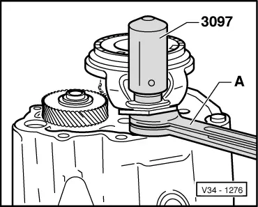
| t | Fitting tool -3097- |
| t | Torque wrench -V.A.G 1331- |
| t | -1-Two-arm puller -Kukko 20/10- |
| t | -2-Matra hooks -V/170- |
| t | -2-Puller hook -Kukko 1-250- |
|
|
|
|
|
|
|
|
|
|
 Note
Note
|
|
|
|
|
|
|
|
|
|
|
|
|
|
|
|
|
|
Note
|
|
|
|
|
|
|
|
|
|
|
|
|
|
|
|
Note
|
|
|
|
|
|
|
|
Note
|
|
|
|
|
|
|
|
|
|
|
|
|
|
| Thickness (mm) | Identification |
| 2.5 | Brown |
| 2.6 | Black |
| 2.7 | Bright metal |
| 2.8 | Copper |
| 2.9 | Brass |
| 3.0 | Blue |
|
Note
|
|
|
|
|
|
Note
|
|
|
|
|
|
|
|
|
|
|
|
Note
|
|
|
|
|
|
|
|
|
|
|
|
|
|
Note
|
|
|
|
Note
|
|
|
|
|
|
|
|