
A3 Mk1
| Renewing needle bearings (polygon bearings) for flange shaft (right-side) with bevel box installed |

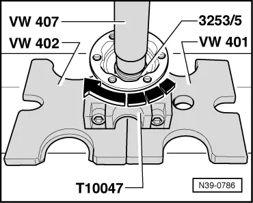
| Special tools and workshop equipment required |
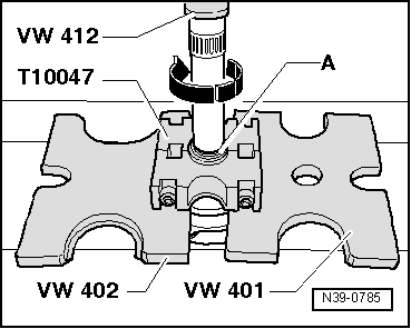
| t | Thrust plate -VW 401- |
| t | Thrust plate -VW 402- |
| t | Press tool -VW 407- |
| t | Press tool -VW 412- |
| t | Assembly tool -VAS 3253- |
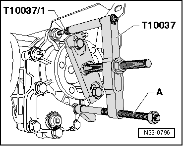
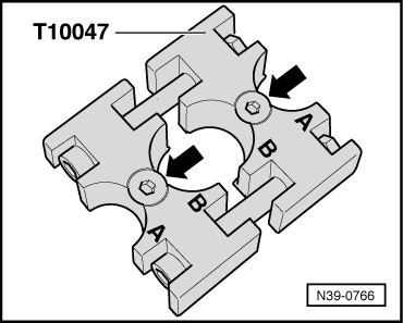
| t | Tensioning tool -T10047- |
|
|
|
|
|
|
|
|
|
|
|
|
|
|
 Note
Note
|
|
|
|
|
|
|
|
|
|
|
|
|
|
|
|
| Component | Nm |
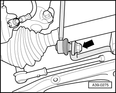
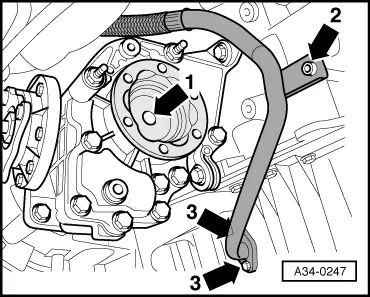
| Flange shaft to gearbox (countersunk bolt) | 25 |
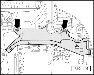
| Heat shield for drive shaft to bevel box | 25 |