audi Workshop Repair Guides

Audi Workshop Service and Repair Manuals

Checking gear oil level in manual gearbox with bevel box and filling up. > < Removing and installing pendulum support
Removing and installing bevel box with gearbox installed
   
Removing and installing bevel box with gearbox installed
Special tools and workshop equipment required
t  Ball joint puller -3287 A-
t  Hexagon key -V.A.G 1669-
t  Used oil collection and extraction unit -V.A.G 1782-

   
Removing
–  On vehicles with one charge air cooler: remove air pipe leading to charge air cooler at longitudinal member (bottom right).
  A10-0396
–  Remove centre noise insulation -arrows-.
  N37-0673
–  Remove noise insulation (right-side) -arrows-.
  A10-1145
–  If fitted, detach cross piece -3- from subframe -1-.
  A40-0271
–  If fitted, unbolt mounting for exhaust system from subframe.
–  Disconnect exhaust system at clamp -arrows-.
–  Push clamp towards the rear.
  V26-0733
–  Mark position of flexible coupling on bevel box flange.
–  Unscrew propshaft with flexible coupling from bevel box flange -arrows-.
  Note
Counterhold with a lever on triangle flange when loosening the bolts.
–  Press propshaft horizontally to rear as far as possible.
  Note
  V34-2101
After loosening bolts -A- (⇒ following illustration N34-887) the engine/gearbox assembly will swing slightly to the front.
  Caution
Make sure that the seal -arrow- in the flange of the propshaft is not damaged when removing and installing. If seals are damaged, the propshaft must be renewed.
  V39-1817
–  Unbolt pendulum support at subframe -arrows A-.
–  Carefully press engine/gearbox assembly forwards.
  N34-0887
–  Unscrew nut -arrow- for coupling rod on anti-roll bar (right-side).
  A39-0275
–  Unscrew nut (top) from swivel joint (right-side).
–  Position ball joint puller -3287 A- as shown in illustration and pull off swivel joint.
  Note
To protect thread, leave nut screwed several turns onto ball joint.
–  Turn steering wheel to the left.
  A40-0241
–  Unscrew heat shield for drive shaft on right of bevel box -arrows-.
–  Unbolt drive shaft (right side) from gearbox flange shaft.
–  Lift drive shaft (right-side) up and secure with wire.
  A10-10260
–  Place used oil collection and extraction unit -V.A.G 1782- below gearbox.
–  Remove drain plug -arrow 2- and allow gear oil to drain off.
–  Unscrew bolt for flange shaft (right-side) -arrow 1- using hexagon key -V.A.G 1669-.
  A34-0248
Vehicles with bevel box bracket (metal casting):
–  Unscrew bolts -A ... C- at bevel box bracket.
  Note
It is not possible to remove bracket at this stage. Bracket remains in installation position.
  N34-1067
Vehicles with bevel box bracket (sheet metal version):
–  Remove bolts -A ... C- and take off bevel box bracket.
Continued for all vehicles:
–  Remove bolts securing bevel box to gearbox.
–  Detach bevel box from gearbox.
–  Remove bevel box.
Installing
Installation is carried out in reverse sequence; note the following:
  N34-1471
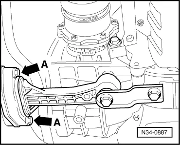
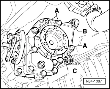
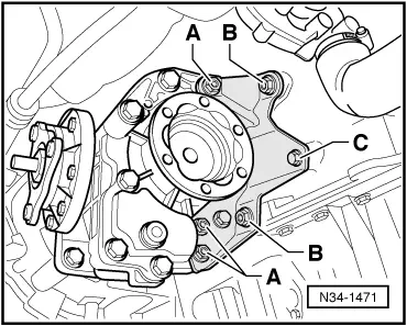
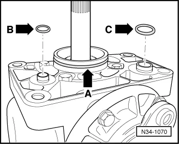
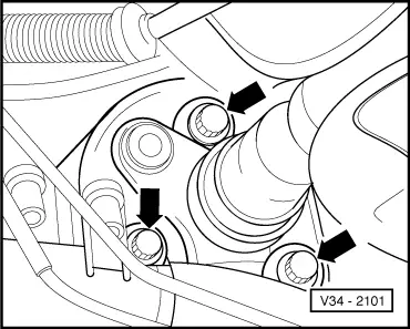
–  Always renew O-ring between bevel box and gearbox -arrow A- and seals on oil supply drillings -arrow B, C-.
–  Lightly lubricate O-ring and seals prior to installing.
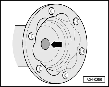
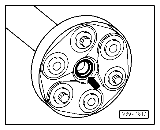
–  Push bevel box completely onto gearbox, at the same time ensuring that the splines on the bevel box input shaft are guided centrally onto the differential connecting piece.
l  If the splines are correctly positioned and the components are located centrally, the bevel box will slide against the gearbox onto the stop.
  Note
Do not use the securing bolts to pull the bevel box onto the gearbox. This could cause the bevel box to tilt and the securing eyes may break off.
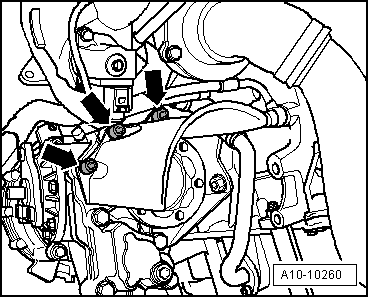
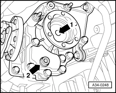
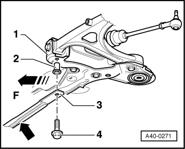
–  Install bevel box bracket prior to fitting bevel box/gearbox securing bolts.
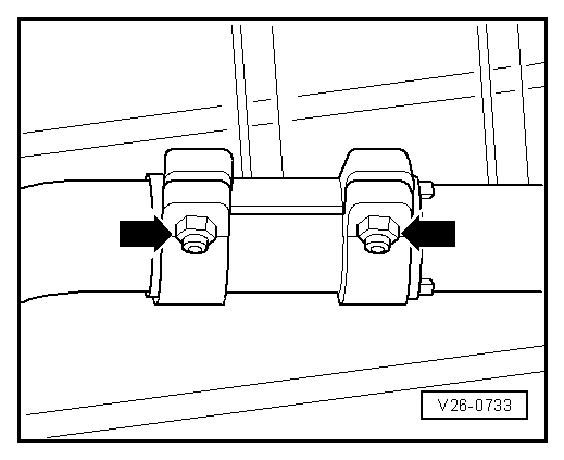
–  Tighten new securing bolts between bevel box and gearbox.
  N34-1070
Vehicles with bevel box bracket (metal casting):
–  Screw in bevel box bracket bolts -A ... C- only a few turns at this stage.
  N34-1067
–  Observe the further tightening sequence:
1.  First tighten bolts -A- to 3 Nm.
2.  Tighten bolts -B- and -C- to 35 Nm.
3.  Tighten bolts -A- to 45 Nm.

   
Vehicles with bevel box bracket (sheet metal version):
–  Screw in bevel box bracket bolts -A ... C- only a few turns at this stage.
  N34-1471
–  Observe the further tightening sequence:
1.  First tighten bolts -A- to 3 Nm.
2.  Tighten bolts -B- to 35 Nm.
3.  Tighten bolt -C- to 22 Nm.
4.  Tighten bolts -A- to 45 Nm.

   
Continued for all vehicles:
–  Tighten bolt for flange shaft (right-side) -1- using hexagon key -V.A.G 1669-.
–  Bolt drive shaft (right-side) to gearbox flange shaft → Running gear, front-wheel drive and four-wheel drive; Rep. Gr.40.
  A34-0256
–  Install heat shield for drive shaft (right-side) -arrows-.
–  Press engine/gearbox assembly towards bulkhead; the bevel box pin must be guided carefully into the propshaft flange when doing this.
  A10-10260
–  Slide propshaft onto guide pin without tilting.
  Caution
The seal -arrow- in the propshaft flange must not be damaged when removing and installing. If seals are damaged, the propshaft must be renewed.
  V39-1817
–  Bolt on pendulum support at subframe -arrows A-.
–  Use new bolts.
  N34-0887
–  Bolt propshaft to flexible coupling on bevel box flange -arrows-: → Rear final drive 02D; Rep. Gr.39.
–  Install exhaust system free of stress → Rep. Gr.26.
–  Install swivel joint and coupling rod → Running gear, front-wheel drive and four-wheel drive; Rep. Gr.40.
  V34-2101
–  Where fitted, secure cross piece -3- to subframe -1- using new bolts and locking fluid -D 000 600 A2-.
Installation position: Marking “L” or “links” (left-side) must be positioned on the left as seen in direction of travel. Foam strip faces downwards -arrow-.
–  Fill up gear oil in manual gearbox with bevel box → Chapter.
  A40-0271
ComponentNm
Bevel box to gearbox40 + 45° 1) 2)
Flange shaft to gearbox25
Heat shield for drive shaft to bevel box25
Pendulum support to subframe20 + 90° 1) 3)
Cross piece to subframe (if fitted)30 + 90° 1) 3) 4)
l  1) Renew bolts
l  2) 45° is equivalent to an eighth turn
l  3) 90° is equivalent to a quarter turn
l  4) Apply locking fluid -D 000 600 A2- when fitting


Checking gear oil level in manual gearbox with bevel box and filling up. > < Removing and installing pendulum support