| Component | Nm |
| Flywheel cover plate to gearbox | 10 |
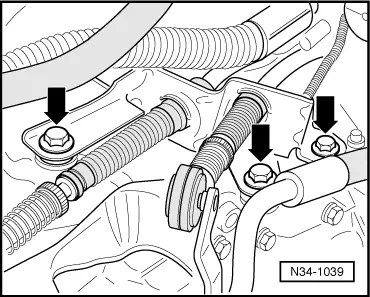
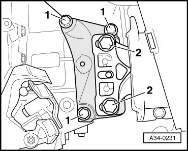
| Gearbox support to gearbox | 40 + 90° 1) 2) |
| Gearbox console to gearbox mounting | 60 + 90° 1) 2) |
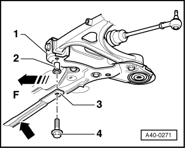
| Pendulum support to | gearbox | 40 + 90° 1) 2) |
| | subframe | 20 + 90° 1) 2) |
| Cross piece to subframe (if fitted) | 30 + 90° 1) 2) 4) |
| Heat shield to gearbox | 25 |
| Heat shield to gearbox | 25 |
| Flywheel cover plate to gearbox | 10 |
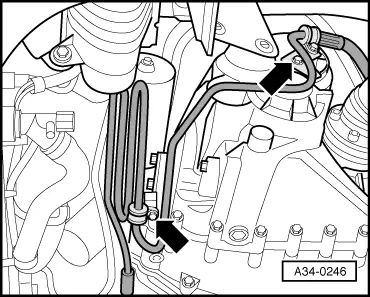
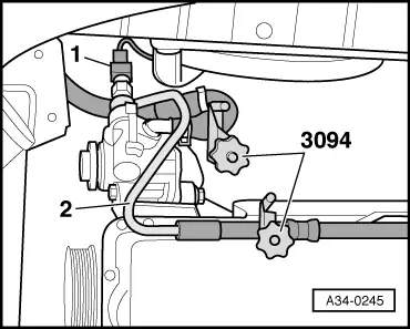
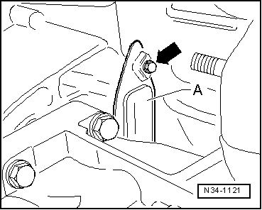
| Pressure pipe of power steering to gearbox support | 22 |
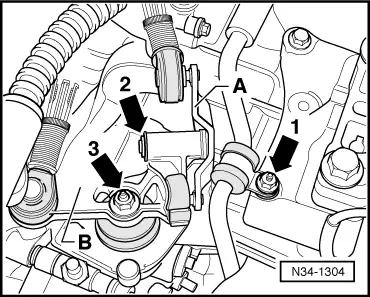
| Selector cable support bracket to gearbox | 23 |
| Selector shaft lever to selector shaft | 20 3) |
| Air cleaner housing to body | 10 |
| Air pipe to longitudinal member | 10 |
| l
| 2) 90° = one quarter turn |
| l
| 4) Apply locking fluid -D 000 600 A2- when fitting |
|

 Note
Note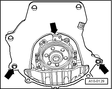
 Caution
 WARNING