
A3 Mk1
| Dismantling and assembling input shaft |

| Special tools and workshop equipment required |
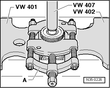
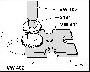
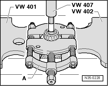
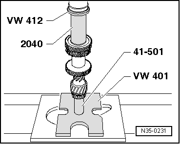
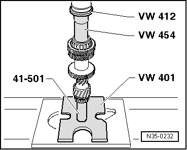
| t | Thrust plate -VW 401- |
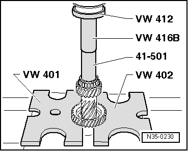
| t | Thrust plate -VW 402- |
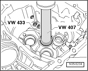
| t | Press tool -VW 407- |
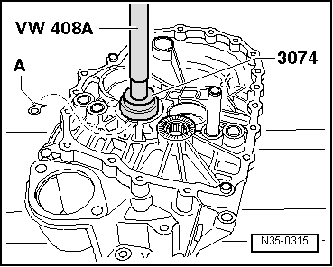
| t | Press tool -VW 408 A- |
| t | Press tool -VW 412- |
| t | Tube -VW 416 B- |

| t | Press tool -VW 433- |
| t | Press tool -VW 454- |
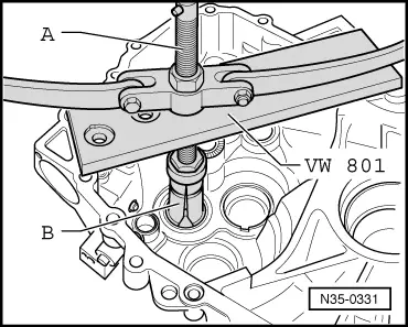
| t | Support plate -VW 801- |
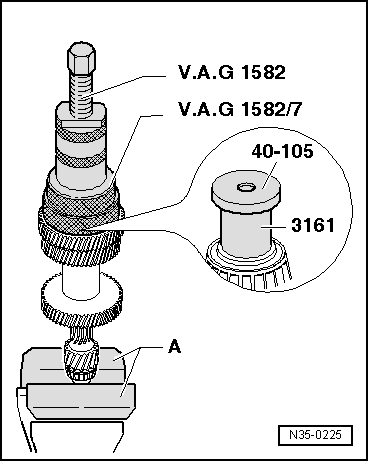
| t | Tapered roller bearing puller -V.A.G 1582- |
| t | Adapter -V.A.G 1582/7- |
| t | -1-Internal puller -Kukko 21/7- |
| t | -3-Splitter -Kukko 17/2- |
| t | -4-Counter-support -Kukko 22/2- |

| t | Thrust plate -40-105- |
| t | Drift sleeve -41-501- |
| t | Tube -2040- |
| t | Thrust piece -2050- |
| t | Thrust plate -3074- |
| t | Extension -3161- |
| Input shaft - exploded view of components |
 Note
Note| t | Refer to technical data when installing new gears → Chapter. |
| t | The input shaft must be re-adjusted if the position of tapered roller bearings is affected when renewing parts. Table of adjustments → Chapter. |

| 1 - | Gearbox housing |
| 2 - | Shim |
| q | Determining thickness → Chapter |
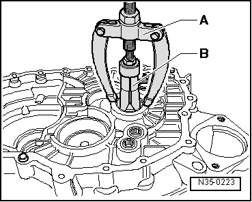
| 3 - | Tapered roller bearing outer race |
| q | Pulling out → Fig. |
| q | Pressing in → Fig. |
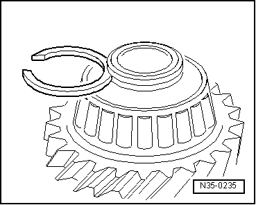
| 4 - | Circlip |
| q | When tapered roller bearing → Item or input shaft → Item are renewed: determine thickness of required circlip → Fig. |
| 5 - | Tapered roller bearing inner race |
| q | Pulling off → Fig. |
| q | Pressing on → Fig. |
| 6 - | 5th gear wheel |
| q | Pressing off → Fig. |
| q | Pressing on → Fig. |
| 7 - | 3rd/4th and 6th gear wheels |
| q | Pressing off → Fig. |
| q | Pressing on → Fig. |
| 8 - | Input shaft |
| q | Adjusting → Chapter |
| 9 - | Tapered roller bearing inner race |
| q | Pressing off → Fig. |
| q | Pressing on → Fig. |
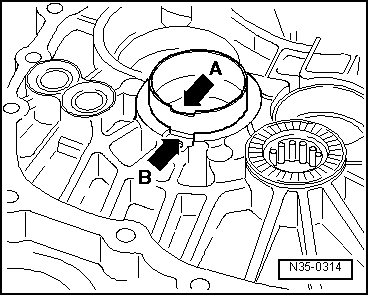
| 10 - | Tapered roller bearing outer race |
| q | Pulling out → Fig. |
| q | On gearboxes from manufacture date 06 04 0: secured with locking plate → Item and bolt → Item |
| q | Installation position on gearboxes from manufacture date 06 04 0 → Fig. |
| q | Pressing in → Fig. |
| q | Renew bolt for locking plate and tighten to 12 Nm. |
| 11 - | Clutch housing |
| q | On gearboxes from manufacture date 06 04 0: with additional threaded hole and recess for locking plate to secure tapered roller bearing outer race → Item |
|
|
|
|
|
|
|
|
|
|
|
|
 WARNING
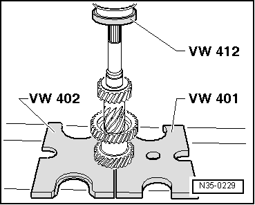
|
|
|
|
|
|
|
|
| Circlips available (in mm) → Note | ||
| 1.79 | 1.89 | 1.98 |
| 1.83 | 1.92 | |
| 1.86 | 1.95 | |
|
|
|
|
|
|
|