
A3 Mk1
|
Dismantling and assembling output shaft, 1st-4th gear
Dismantling and assembling output shaft, 1st-4th gear
|
 |
|
|
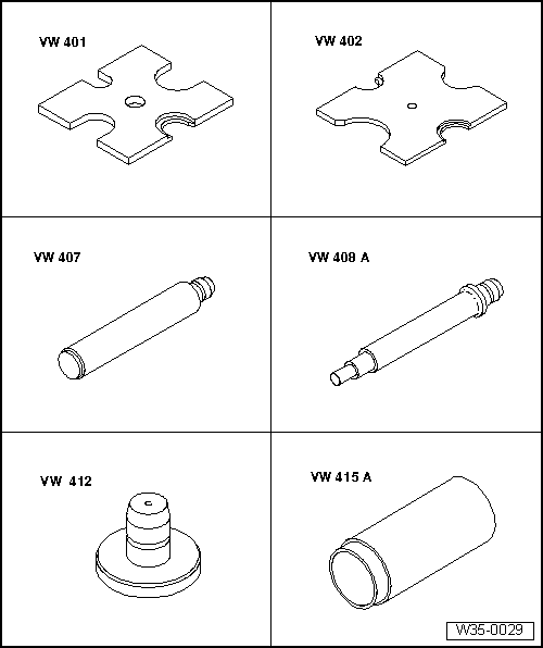
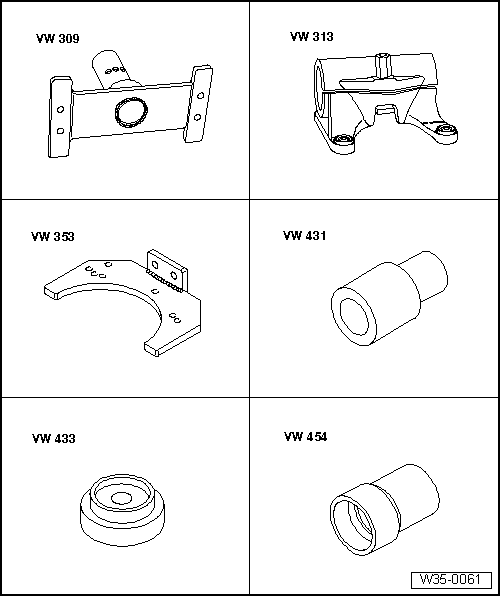
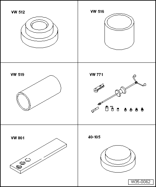
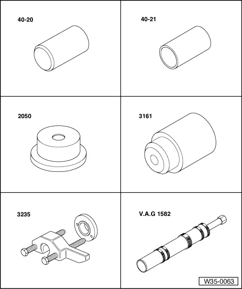
Special tools and workshop equipment required
|
 |
|
|
Special tools and workshop equipment required
|
 |
|
|
Special tools and workshop equipment required
|
 |
|
|
Special tools and workshop equipment required
|
 |
|
|
Special tools and workshop equipment required
|
 |
|
|
 |
|
|
Notes:
|
|
|
|
|
|
|
|
|
|
|
|
|
|
|
|
 |
|
|
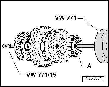
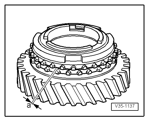
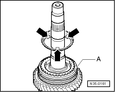
→ Fig.1 Pulling dished washer -A- out from output shaft |
 |
|
|
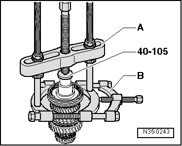
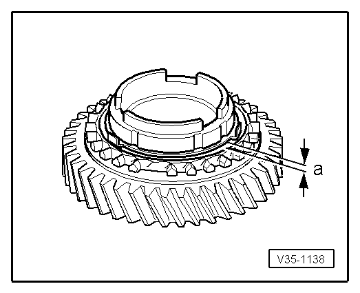
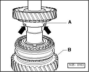
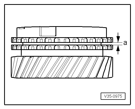
→ Fig.2 Pressing dished washer -A- in output shaft onto stop |
 |
|
|
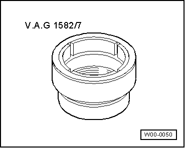
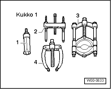
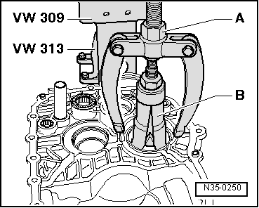
→ Fig.3 Pulling taper roller bearing outer race out from gearbox housing A - Counter support, e.g. Kukko 22/2 A - Internal puller 56 ... 70 mm, e.g. Kukko 21/8 |
 |
|
|
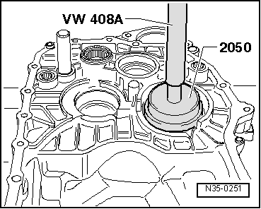
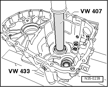
→ Fig.4 Pressing taper roller bearing outer race into gearbox housing
|
 |
|
|
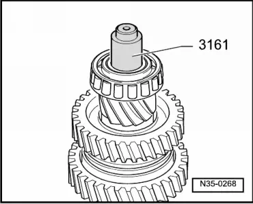
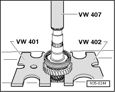
→ Fig.5 Pulling off taper roller bearing inner race
|
 |
|
|
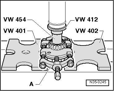
→ Fig.6 Pulling off 3rd and 4th gear synchro-hub/locking collar over 4th gear wheel
A - Puller, e.g. Kukko 18/2 B - Separating device 22 ... 115 mm, e.g. Kukko 17/2 |
 |
|
|
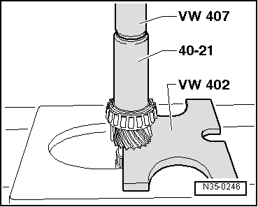
→ Fig.7 Pressing off 1st and 2nd gear locking collar and synchro-hub After removing securing ring press 2nd gear sliding wheel and locking collar/synchro-hub off together. |
 |
|
|
→ Fig.8 Pulling off taper roller bearing inner race A - Separating device 22 ... 115 mm, e.g. Kukko 17/2 |
 |
|
|
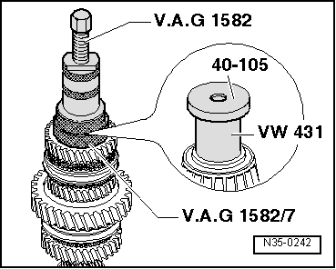
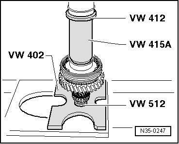
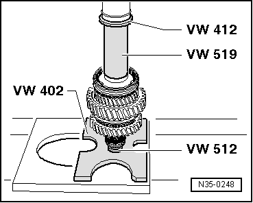
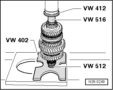
→ Fig.9 Pressing on taper roller bearing inner race |
 |
|||||||
|
→ Fig.11 Checking 1st, 2nd and 3rd gear synchro-rings for wear
|
 |
|
|
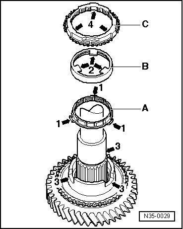
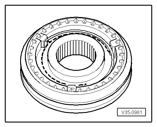
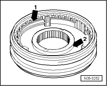
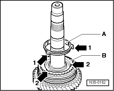
→ Fig.12 Installation position of outer ring, inner ring and 2nd gear synchro ring
Angled lugs (arrow 1) point towards outer ring -B-.
Lugs (arrow 2) engage in gear wheel recesses (arrow 3).
The recesses (arrow 4) engage in lugs (arrow 1) of inner ring -A-. |
 |
|
|
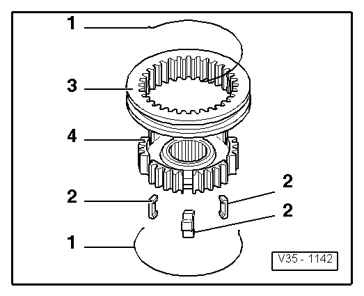
→ Fig.13 Dismantling and assembling 1st and 2nd gear locking collar and synchro-hub
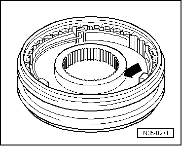
The recesses for locking pieces in synchro-hub and locking collar must align. |
 |
|
|
→ Fig.14 Assembling 1st and 2nd gear locking collar/synchro-hub The locking collar has been pushed over the synchro-hub.
|
 |
|
|
→ Fig.15 Installation position of 1st and 2nd gear locking collar/synchro-hub Identification groove -arrow 1- and narrow collar -arrow 2- of synchro-hub point towards 1st gear. |
 |
|
|
→ Fig.16 Pressing on 1st and 2nd gear locking collar/synchro-hub |
 |
|
|
→ Fig.17 Installation position for 1st or 3rd gear outer ring Lugs (arrows) face towards synchro-hub/locking collar -A- |
 |
|
|
→ Fig.18 Installation position synchro-ring (inner ring) -A- The lugs (arrows 1) engage in the recesses (arrow 2) in the synchro-ring -B-. |
 |
|
|
→ Fig.19 Installation position 1st and 3rd gear wheel The higher shoulder -A- faces toward 2nd or 4th gear -B-. The recesses in the shoulder (arrows) engage in the lugs of the outer ring (arrow => Fig. 17) |
 |
|
|
→ Fig.20 Installation position 3rd and 4th gear locking collar/synchro-hub The wider shoulder of the synchro-hub (arrow) faces towards 3rd gear. |
 |
|
|
→ Fig.21 Pressing on 3rd and 4th gear synchro-hub with locking collar |
 |
|||||||
|
→ Fig.22 Checking synchro-ring for wear
|
 |
|
|
→ Fig.23 Pressing on taper roller bearing inner race |
 |
|||||||||||||||||
|
→ Fig.24 Determining thickness of circlip
The following securing clips are available:
|
 |
|
|
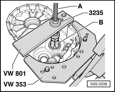
→ Fig.25 Pulling taper roller bearing outer race out from gearbox housing A - Counter support, e.g. Kukko 22/2 B - Internal puller 46...58 mm, e.g. Kukko 21/7 |
 |
|
|
→ Fig.26 Pressing taper roller bearing outer race into gearbox housing
|