
A3 Mk1
|
 WARNING
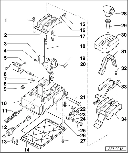
| 1 - | Bolt |
| q | 8 Nm |
| 2 - | Locking segment |
| 3 - | Contact spring |
| q | For selector lever position indicator |
| 4 - | Bolt |
| q | 4 Nm |
| q | Shift selector lever into position “P” to loosen and tighten. |
| 5 - | Bolt |
| q | 2x |
| q | 1.5 Nm |
| 6 - | Selector lever lock solenoid -N110- |
| q | Function test → Chapter |
| q | Removing and installing → Chapter |
| 7 - | Nut |
| q | Renew |
| q | 13 Nm |
| 8 - | Washer |
| 9 - | Nut |
| q | With shoulder |
| q | 25 Nm |
| 10 - | Shift unit |
| 11 - | Locking cable |
| q | Do not bend or kink |
| q | Removing and installing → Chapter |
| q | Adjusting → Chapter |
| 12 - | Selector lever cable |
| q | Do not bend or kink |
| q | Renew selector lever cable if rubber sleeve is damaged |
| q | Removing and installing → Chapter |
| q | Before installing, lightly lubricate ball socket with polycarbamide grease -G 052 142 A2-. |
| q | Adjusting → Chapter |
| 13 - | Retaining clip |
| q | For selector lever cable sleeve |
| 14 - | Bottom cover |
| q | For shift unit |
| 15 - | Bolt |
| q | 7 Nm |
| 16 - | Washer |
| 17 - | Detent spring |
| q | With roller |
| 18 - | Selector lever |
| q | With release |
| q | Removing and installing → Chapter |
| 19 - | Roller |
| 20 - | Circlip |
| 21 - | Bolt |
| q | Splined |
| q | Only counterhold at bolt head, do not turn! |
| q | Apply grease to shank |
| 22 - | Bolt |
| q | 25 Nm |
| 23 - | Locking lever |
| q | For locking cable |
| q | Locks selector lever in position “P” |
| 24 - | Washer |
| 25 - | Bolt |
| q | Standard bolt 0.5 Nm |
| q | Bolt with shoulder, tightening torque according to bolt diameter |
| 26 - | Seal |
| 27 - | Bolt |
| 28 - | Selector lever handle |
| q | To remove, push sleeve for selector lever -item 29- downwards and remove handle by pulling it upwards |
| q | To install, press handle onto selector lever and pull sleeve upwards to secure |
| 29 - | Sleeve for selector lever |
| 30 - | Selector gate |
| q | Clipped onto frame -item 34- |
| q | To remove, carefully release securing lugs |
| 31 - | Cover strip |
| q | Clipped onto frame -item 34- |
| 32 - | Bolt |
| 33 - | Selector lever position display |
| q | With contact plate and connector |
| 34 - | Frame |
| q | Attached onto sift unit |
| q | To remove, carefully compress retaining lugs at 4 securing points |