audi Workshop Repair Guides

Audi Workshop Service and Repair Manuals

Transporting the automatic gearbox > < Measuring system pressure
Removing and installing gearbox
   
Removing and installing gearbox
Special tools and workshop equipment required
t  Support bracket -10 - 222 A-
t  Support bridge -30-211 A-
t  Hose clamps, up to 25 mm -3094-
t  Gearbox support -3282-
t  Adjustment plate -3282/2-
t  Engine and gearbox jack -V.A.G 1383 A-
t  15 mm socket attachment Matra V/175

   
Removing
–  Remove engine cover panel.
–  Remove air hose -1-.
–  Vehicles with TDI engine: detach breather hose -3-.
–  Unplug electrical connector -2- from air mass meter -G70-.
–  Remove bolts -4- and -5-, detach air cleaner housing.
  Caution
Follow steps required when disconnecting battery → Rep. Gr.27.
–  Switch off ignition.
–  Disconnect battery → Rep. Gr.27.
–  Remove battery and battery tray → Rep. Gr.27.
  A37-0192
–  Unplug electrical connectors:
1 - to solenoid valves (10-pin connector)
2 - to vehicle speed sender -G68-
3 - on multifunction switch -F125-
4 - on gearbox speed sender -G38-
  Note
There are two versions of gearbox speed sender -G38-: connection with and without integral wire.
–  Disengage wiring harness from retainers and guide out to side.
  A37-0193
–  Use screwdriver to pry selector lever cable -1- off selector shaft lever -4-, detach retaining clip -3- from cable support bracket.
–  Detach selector lever cable and move clear to one side.
  Note
Do not bend or kink the selector lever cable.
  A37-0194
–  Unbolt power steering pressure pipe from gearbox -arrows-.
  A10-0938
–  Disconnect earth wire -1-.
–  Detach wiring -3- and -4- at starter.
–  Unplug connector -2- and pull out of bracket.
–  Disengage wiring from bracket on starter and move clear to one side, remove bracket.
  A37-0195
–  Clamp off coolant hoses with hose clamps -3094- and detach hoses from ATF cooler.
  Note
Seal off connections on ATF cooler with clean plugs or sealing caps to prevent dirt from entering.
  A37-0196
–  Set up support bracket -10 - 222 A- with adapters -10 - 222 A /3- on wing mounting flanges (left and right), as shown in illustration.
–  Hook spindles into engine lifting eyes and slightly take up weight of engine/gearbox assembly via the spindles.
  A37-0197
–  Remove centre noise insulation (loosen fasteners -arrows-).
  N37-0673
–  Remove left and right noise insulation -arrows-.
  N37-0674
Vehicles with charge air cooler:
–  Detach air pipe leading to charge air cooler from longitudinal member (bottom right) -arrows-.
  A10-0396
Continued for all vehicles:
–  Remove bolts -arrows- and detach guard plate from gearbox.
  A37-0199
–  If fitted, remove bolts -arrows- and detach heat shield for drive shaft (right-side).
–  Unbolt drive shafts from gearbox flanges.
–  Lift drive shaft (right-side) up and secure with wire.
–  Move drive shaft (left-side) clear towards the rear and secure with wire.
  Note
  A10-0921
The flexible pipe connection (de-coupling element) in the front exhaust pipe must not be bent more than 10° - otherwise it can be damaged.
–  Disconnect exhaust system at clamp -arrows-.
  V26-0733
–  First remove bolts -A-, then bolts -B- and detach pendulum support.
–  Remove plug from opening in torque converter cover plate.
  N34-0712
–  Using 15 mm socket Matra V/175, unscrew 3 nuts -arrow- from torque converter (rotate crankshaft 1/3 turn for each nut).
  Note
To loosen the torque converter nuts, counterhold at bolt for vibration damper.
  A37-0201
–  If fitted, disengage rubber mount at front exhaust pipe -arrow-.
–  Remove bolts -2- for steering box.
  A34-0238
–  Lever off steering box from dowel sleeve on subframe -arrow-.
–  Remove bracket for power steering pipe from subframe.
–  Position engine and gearbox jack -V.A.G 1383 A- below subframe (place a block of wood in between).
  A40-0305
–  Remove subframe bolts -1- and -3-.
–  Lower subframe approx. 100 mm (subframe supports itself).
  A34-0238
–  Unbolt gearbox support (left-side) from gearbox -arrows-.
–  Remove all engine/gearbox securing bolts which are accessible from above.
  A37-0203
–  Adjust spindles at support bracket -10 - 222 A- to lower gearbox by distance -a-.
l  Dimension -a- = 60 mm
  A37-0204
–  Set up gearbox support -3282- on engine and gearbox jack -V.A.G 1383 A-.
–  Place adjustment plate -3282/2- on gearbox support -3282- (adjustment plate only fits in one position).
–  Align arms of gearbox support according to holes in adjustment plate.
–  Secure support elements as illustrated on adjustment plate.
  V37-1049
–  Place engine and gearbox jack -V.A.G 1383 A- with gearbox support -3282- underneath gearbox and support gearbox.
  N37-0079
–  Place safety support pin on ATF oil pan and secure to gearbox housing -arrow-.
  N37-0059
–  Turn the drive flange (right-side) so that the flat -arrow- is vertical.
–  Remove starter.
–  Remove all engine/gearbox securing bolts which are accessible from below.
–  Push gearbox off engine and at the same time press torque converter out of drive plate.
–  Press torque converter into gearbox housing.
–  Slightly lower gearbox, guiding the power steering pipe past the gearbox.
–  Carefully lower gearbox a bit further.
  N37-0680
–  Secure torque converter in gearbox using support bridge -30 - 211 A- to prevent it from falling out.
Installing
  Note
t  Tightening torques apply only to lightly greased, oiled, phosphated or black-finished nuts and bolts.
t  Additional lubricant such as engine or gear oil may be used, but do not use graphite lubricant.
t  Do not use parts which have been degreased.
t  Tolerance for tightening torques ±15%.
l  Tightening torques → Chapter, → Fig.
  N37-0702
l  Engine/gearbox securing bolts:
  A37-0214
ItemBoltNm
1, 2M12x6580
3, 4M12x18080
5, 6, 7M10x5045
8M12x8080
ADowel sleeves for centralising

l  Additional tightening torques:
   
ComponentNm
Drive plate to torque converterM10 x 157
Heat shield for drive shaft to cylinder block35

Installation is carried out in reverse sequence; note the following:
  Note
t  Before fitting a replacement gearbox, always clean the ATF cooler.
t  Renew bolts which are tightened by turning through a specified angle.
t  Renew self-locking nuts and bolts, and seals, O-rings and gaskets.
t  Hose connections and hoses for charge air system must be free from oil and grease before fitting.
t  Secure all hose connections with the correct hose clips (as original equipment); refer to → Electronic parts catalogue.
t  To ensure that the charge air hoses can be connected securely, you must spray the screws on used screw-type clips with rust remover prior to installation.
t  If a new torque converter with integrated needle bearing is installed in a gearbox with a sleeve bearing in the turbine shaft, the sleeve bearing must be removed → Chapter.
–  Press torque converter hub through oil seal as far as first stop.
   
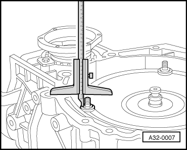
–  Turn the torque converter, at the same time pressing it inwards lightly until the slots on the torque converter hub engage in the drive lugs on the ATF pump gear and the torque converter slides in a noticeable distance.
l  
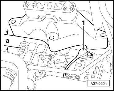
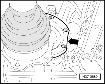
If the torque converter is correctly installed, the depth between the contact faces at the bottom of the studs on the torque converter and the contact surface of the torque converter bellhousing is about 22 mm.
  WARNING
t  If the torque converter has not been fully inserted, the distance will be only approx. 10 mm.
t  If the torque converter is not fitted correctly, the drive lugs on the torque converter or the ATF pump will be seriously damaged when the gearbox is joined to the engine.
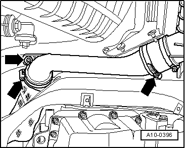
–  Before installing, ensure that the dowel sleeves on the engine are correctly seated.
–  Fit intermediate plate onto dowel sleeves.
–  When pushing the engine and gearbox together, ensure that no wiring or pipes etc. can become trapped.
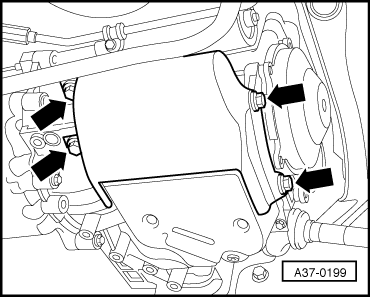
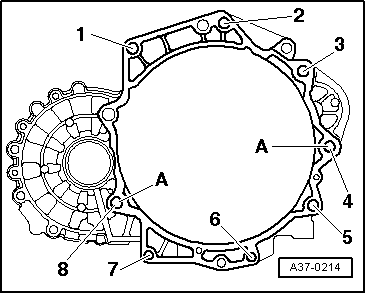
–  Secure gearbox to engine.
–  Use genuine nuts for attaching torque converter to drive plate → Electronic parts catalogue.
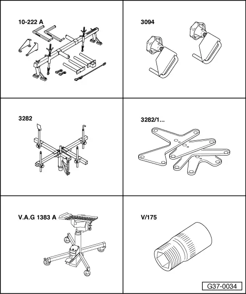
–  Use special tool Matra V/175 to tighten nuts of torque converter.
–  Install subframe → Rep. Gr.40.
–  Fit drive shafts to gearbox → Rep. Gr.40.
–  Install pendulum support → Chapter.
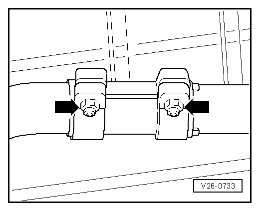
–  Align exhaust system so it is free of stress → Rep. Gr.26.
–  Observe correct procedure after connecting battery → Rep. Gr.27.
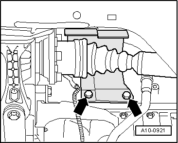
–  Move selector lever to position “P” and install selector lever cable → Chapter.
–  Check adjustment of selector lever cable and adjust if necessary → Chapter.
–  Perform basic setting → Rep. Gr.01.
–  Check gear oil level in final drive → Chapter.
–  Check and top up ATF level → Chapter.
–  Install noise insulation → Rep. Gr.50.
–  If rumbling noises occur when driving, adjust assembly mountings → Rep. Gr.10.
  Caution
Perform wheel alignment after installation.
  A32-0007

Transporting the automatic gearbox > < Measuring system pressure