A3 Mk1
 Note
Note
|
|
|
|
|
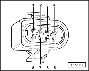
| Connector Contact | -V.A.G 1598/18A- Socket | Connector Contact | -V.A.G 1598/18A- Socket |
| 1 | 63 | 5 | 18 |
| 2 | 40 | 6 | 62 |
| 3 | 1 | 7 | 23 |
| 4 | Contact vacant | 8 | Contact vacant |
Note
|
|
|

Note
|
|
|
|
|
| Connector Contact | -V.A.G 1598/18A- Socket | Connector Contact | -V.A.G 1598/18A- Socket |
| 1 | 63 | 5 | 18 |
| 2 | 40 | 6 | 62 |
| 3 | 1 | 7 | 23 |
| 4 | Contact vacant | 8 | Contact vacant |
Note
|
|
|