audi Workshop Repair Guides

Audi Workshop Service and Repair Manuals

Automatic gearbox, gears, control > < Dismantling gearbox
Assembling gearbox
Assembling gearbox
Special tools and workshop equipment required
   
t  Spacer pin -T10317-
  W00-10371
t  Straightedge -T40100-
t  Cleaning fluid -D 009 401 04-
t  Sealant -D 176 404 A2-
  W00-10297
–  Install freewheel.
Note the position of the smallest lug -arrow-. The freewheel can only be fitted in one position.
All the components referred to below have a similar small lug. The lugs must always be aligned one above the other.
  Note
In the following description the parts are shown in a cut-away section of the gearbox for more clarity.
  N37-10235
The cutaway view shows the position of the freewheel when installed in the gearbox.
The freewheel is secured with a circlip.
  N37-10237
–  Install circlip -arrows-.
The open part of the circlip faces towards the selector shaft -1-. It is important to position the ends of the circlip as shown in this illustration.
  N37-10236
–  Fit first outer plate of brake „B1“ with smooth side facing upwards.
There is a shoulder on the underside, which is provided for the circlip securing the freewheel.
Once again, note the position of the smallest lug; the outer plates also fit in one position only.
–  Fit first inner plate of „B1“.
–  Install all remaining plates alternately.
Fit last outer plate with a thickness of approx. 2.5 mm.
–  Position splines of inner plates so they are in line.
Doing this now will facilitate the installation of clutch „K1“ at a later stage.
  N37-10238
–  Fit dished spring -A- with convex side facing upwards.
  N37-10239
The outer edge of the dished spring -A- will then lie on the last outer plate.
  N37-10240
–  Fit spring seat.
  N37-10241
–  Fit spring.
  Note
Now inspect the „B1“ piston; there are a lug and a drilling on the outer circumference.
l  The „B1“ piston must not be inserted while the valve body is installed.
  N37-10242
–  Fit „B1“ piston as shown in illustration.
  N37-10243
–  Carefully guide spindle -3253/3- from assembly tool -3253- through spur gear; the bush on the lower end must not be damaged.
–  Using assembly tool -T10064/1-, -T10064/6A- and spindle -3253/3-, press down piston as far as stop.
  N37-10244
–  Install circlip -arrows-.
  Note
The special tools are omitted from the illustration to show the location of the circlip more clearly.
The open section of the circlip faces towards the aperture for the brake with brake band. As before, it is important to position the ends of the circlip as shown in this illustration.
  N37-10245
Now check position of piston.
l  The -drilling--arrow- in the piston must be visible in the aperture for the valve body.
–  Remove assembly tool again.
  N37-10246
–  Stick needle bearing to clutch „K1“ with vaseline
The dark side of the needle bearing faces towards the gearbox.
–  Carefully insert clutch „K1“.
  N37-10247
–  Turn clutch anti-clockwise in direction of -arrow- so it slides into freewheel.
  N37-10249
If the clutch is correctly installed, the edges -A- of the bearing seat will be level with the edges -B- of the clutch.
  N37-10248
–  Fit needle bearing for annulus.
  N37-10250
–  Stick thrust washer to annulus with vaseline.
The washer can only be fitted in one position.
  N37-10251
–  Turn annulus in both directions when installing.
  N37-10252
–  Fit needle bearing for planet carrier.
  N37-10253
–  Stick thrust washer to planet carrier with vaseline.
–  Turn planet carrier in both directions when installing.
  N37-10254
–  Insert axial needle bearing for large sun gear.
  N37-10255
–  Install large sun gear.
  N37-10256
–  Stick axial needle bearing to planet carrier with vaseline.
The dark side of the axial needle bearing faces towards the planet carrier.
  N37-10257
–  Turn planet carrier in both directions when installing.
  N37-10258
When the planet carrier is correctly installed, the splines on the outside circumference engage in the clutch cage of „K1“.
  N37-10259
–  Fit axial needle bearing for annulus.
  N37-10260
–  Stick thrust washer in annulus with vaseline.
The washer can only be fitted in one position.
–  Turn annulus in both directions when installing.
  N37-10261
–  Stick axial needle bearing to annulus with vaseline.
  N37-10262
–  Install annulus.
  N37-10263
–  Fit first outer plate of brake „B2“.
It is approx. 4.2 mm thick.
The outer plates only fit in one position.
  N37-10264
–  Fit first inner plate of „B2“.
–  Then fit all remaining plates; the two outer plates are approx 3 mm thick.
  N37-10265
There are two different versions of the last outer plate for „B2“:
-1- On later gearboxes, one outer plate with a thickness of approx. 7.5 mm is fitted last.
-2- On earlier gearboxes, two outer plates with a thickness of approx. 3.8 mm each are fitted last.
–  Fit circlip.
Before continuing assembly, check clearance of „B2“.
Checking clearance of 2nd, 4th and 5th gear brake „B2“
  N37-10266
–  Measure down to last outer plate of „B2“ and note value.
Example: 26.15 mm
–  Press piston of „B2“ into cover as far as stop.
  N37-10287
–  Measure down from two lugs of „B2“ piston to sealing surface of cover and note value.
Example: 25.37 mm
–  Subtract the two measurements.
Example: 26.15 mm – 25.37 mm = 0.78 mm
Specification: 0.60 ... 0.90 mm
  N37-10288
–  Stick axial needle bearing with vaseline into „K2/K3“.
–  Turn „K2/K3“ in both directions when installing.
  N37-10267
–  Fit axial needle bearing -A-.
–  Fit thrust washer on bearing (it is stuck in cover).
l  Before continuing assembly, first check axial clearance of complete planetary gear set.
  N37-10268
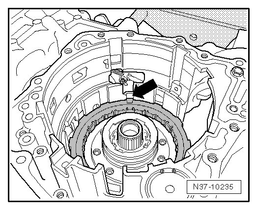
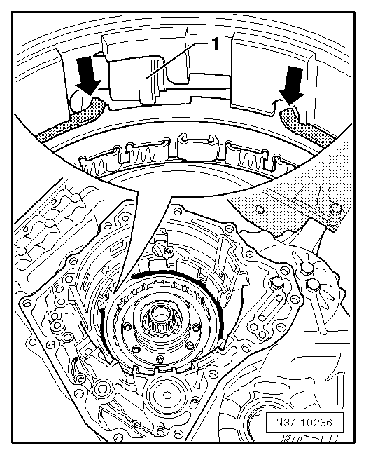
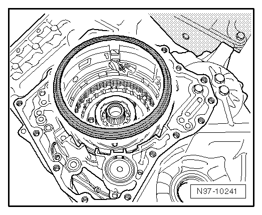
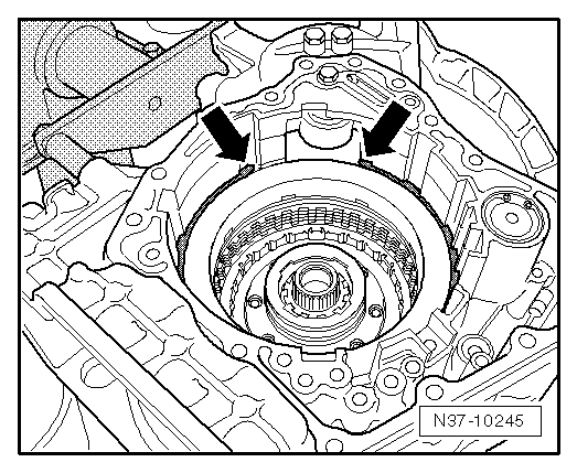
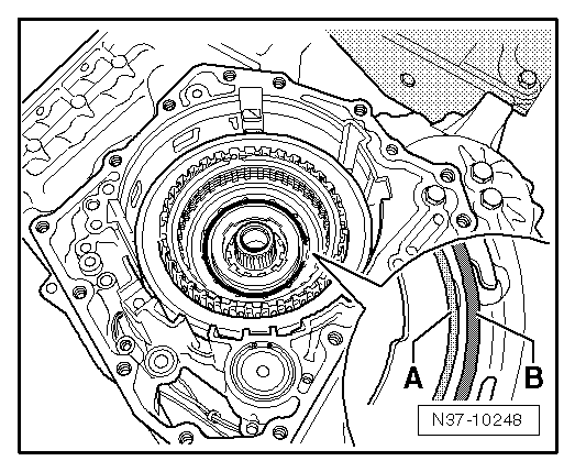
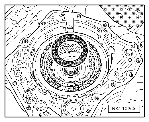
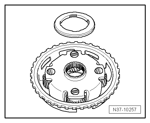
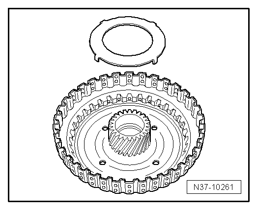
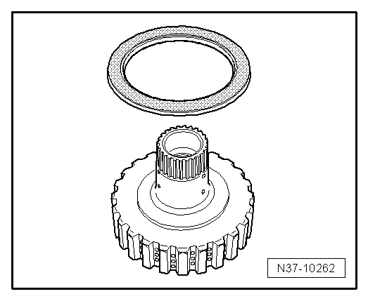
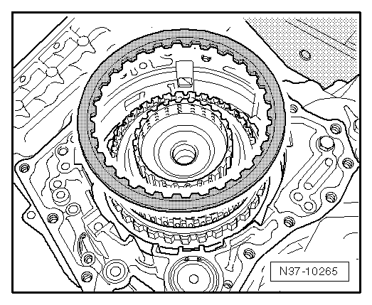
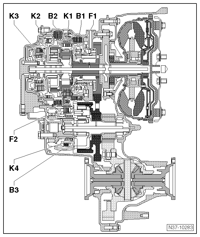
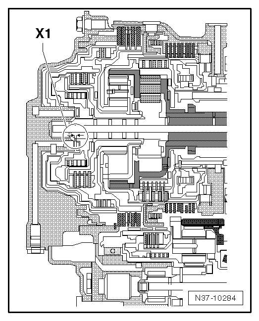
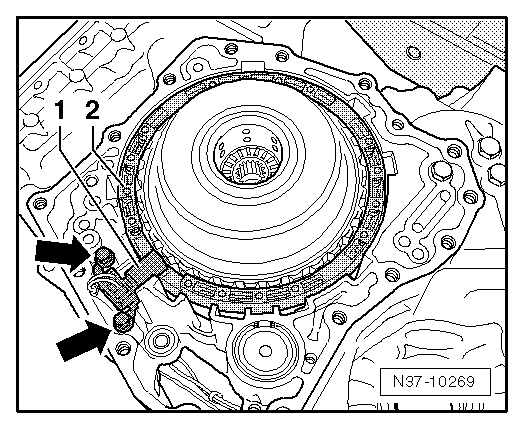
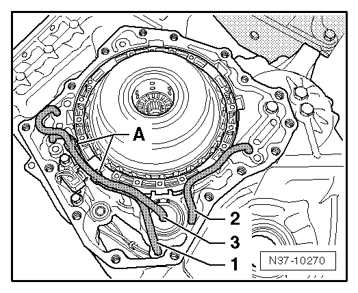
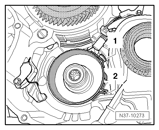
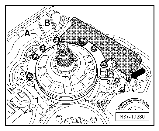
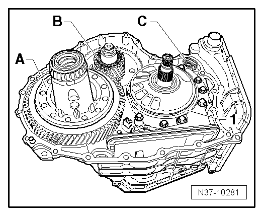
Checking axial clearance of planetary gear set
The following measurements are required in order to check the axial clearance. Before taking these measurements it may be helpful to refer to this illustration, which shows where the axial clearance exists.
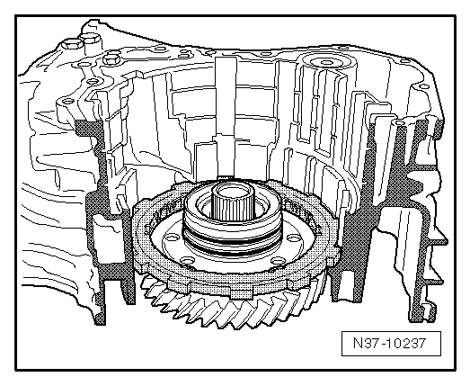
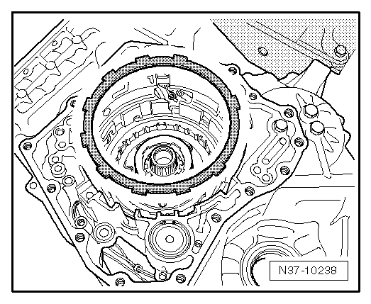
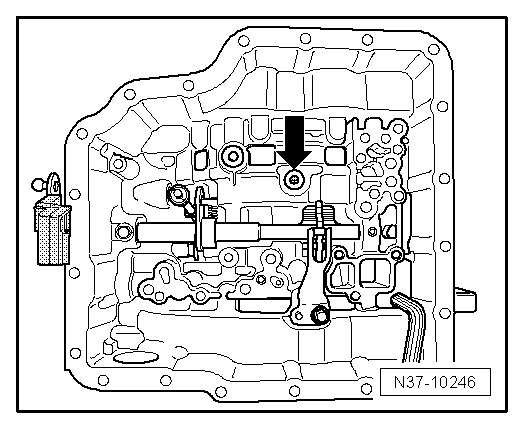
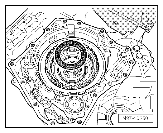
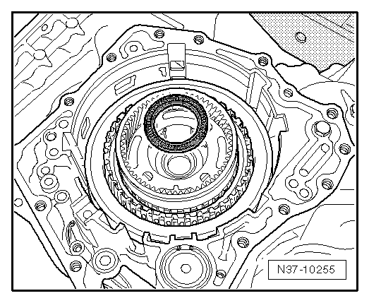
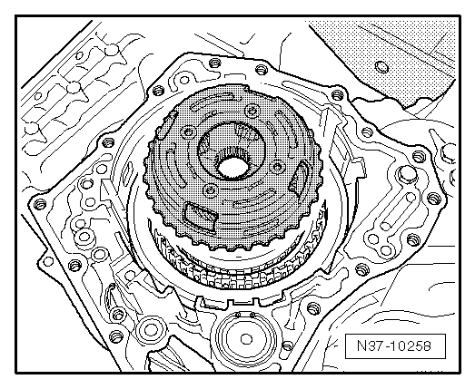
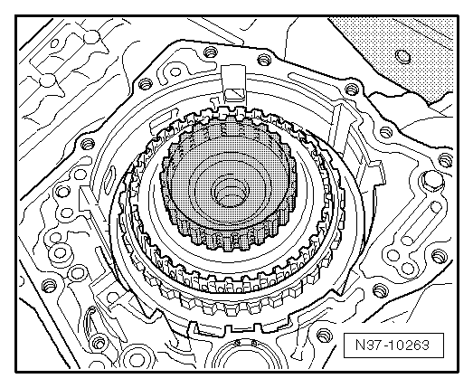
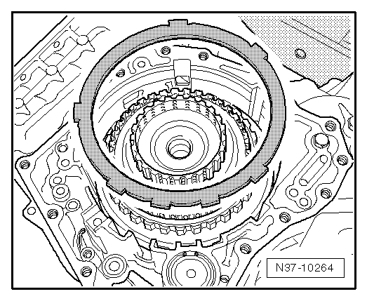
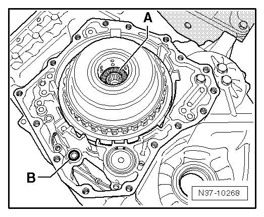
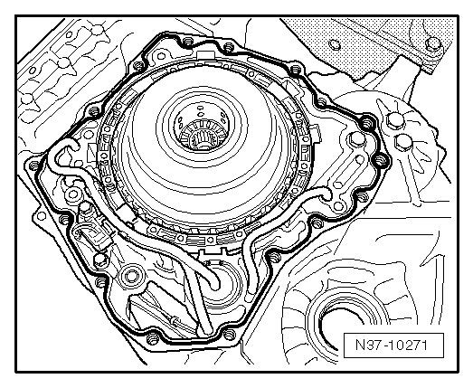
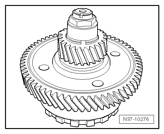
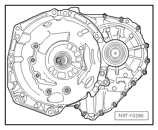
This is an overall view of the gearbox.

   
–  The first clearance to be measured is at the location marked -x1-.
Determining x1
Three measurements are now required in order to obtain the two values „a“ and „b“.
Determining dimension »a«:
  N37-10284
–  Attach spacer pins -T10317- to cover with nuts.
Hand-tight is sufficient.
–  Measure down to seat of thrust washer and note value.
Example: 125.30 mm
  N37-10286
–  Measure down to surface of cover and note value.
Example: 107.75 mm
This value represents the height of the measuring tools comprising spacer pins and straight-edge. It will be required again later; note down the value so you do not have to repeat the measurement.
–  Subtract the two measurements.
In our example the values are subtracted as follows: 125.30 mm – 107.75 mm = 17.55 mm = „a“.
–  (Substitute the values you have measured for the figures in the example.)
The result is dimension „a“. Note down this value.
Determining dimension »b«:
  N37-10282
–  Screw spacer pins -T10317- hand-tight into gearbox.
–  Measure down to thrust washer and note measured value.
Example: 90.70 mm
Once again two values have to be subtracted. You have already measured one of the values (107.75 mm in the example) on the contact surface of the cover.
Example: 107.75 mm – 90.70 mm = 17.05 mm = „b“
–  (Substitute the values you have measured for the figures in the example.)
(The value of 107.75 mm in the example comes from the first measurement.)
The result is dimension „b“. Note down this value.
Calculating x1
x1 = »a«»b«
Example: 17.55 mm – 17.05 mm = 0.50 mm
  Note
The resulting value must be within the specification.
Specification: 0.25 ... 0.55 mm
Do not continue assembly unless the specification is obtained. If you have not obtained the specification the assembly is not correct. This must be rectified before proceeding further.
Assembling gearbox (continued)
–  Remove thrust washer again from „K2“ and stick it into cover with vaseline.
  N37-10231
–  Install spring -2-.
The spring can only be fitted in one position.
–  Install gearbox input speed sender -G182--1-.
The ATF lines are installed next. Take care to keep the lines straight when installing and push both ends evenly into the gearbox housing as far as the stop.
  N37-10269
–  First install ATF lines -1- and -2-.
–  Then install ATF line -3- with retainer clips -A-.
  N37-10270
–  Fit new O-ring -B- in gearbox housing.
Installing housing cover for planetary gearing
–  Clean sealing surfaces with cleaning fluid -D 009 401 04-.
  Note
The sealing surfaces must be absolutely free of oil and grease, otherwise leakage can occur.
  N37-10268
–  Stick thrust washer in housing cover with vaseline.
The joint between the housing cover and the gearbox is sealed with sealant -D 176 404 A2-.
  N37-10289
–  Apply a thin 3 mm wide bead of sealant to gearbox housing as shown in illustration.
  Note
A thicker bead of sealant does not give a better seal and may cause malfunctions.
–  Fit housing cover.
  N37-10271
–  First fit bolts -1- and -2- only and screw in by hand.
In this way the O-rings under bolts -1- will be seated properly in the cover.
–  Fit all remaining bolts and screw in by hand.
–  Tighten the two bolts -1- to 35 Nm.
–  Then tighten bolts -2- to 20 Nm.
–  Finally, tighten remaining bolts to 20 Nm.
–  Turn gearbox so that housing cover faces downwards.
  N37-10272
–  Install brake band „B3“.
–  Ensure correct seating in retainer -1- and plunger -2-.
  N37-10273
–  When installing clutch „K4“, lift brake band slightly with a piece of wire.
–  Fit axial needle bearing -1-.
  N37-10274
–  Install gear -A- with circlip facing downwards.
–  Align inner plates of „K4“.
  N37-10275
–  Now pick up planetary gear set III.
  N37-10276
–  Insert it so that the spur gears come into mesh -arrow-.
  N37-10277
–  Turn backwards and forwards until the two spur gears are level in the same plane -arrow A-.
Turning the gears backwards and forwards enables the plates to engage in the plate carrier.
This can best be done using a 32 mm socket with a suitable handle.
  N37-10278
–  Fit turbine shaft -A-, turning in both directions, and insert into gearbox as far as stop.
When the shaft is correctly installed, the lower shoulder -arrow- on the shaft contacts the spur gear.
–  When the ATF pump is being installed, there must be no seal in the groove -1- on the turbine shaft. Remove before installation.
–  Fit gasket -B- for ATF pump on pump flange.
  N37-10279
–  Install ATF pump -A- and ATF strainer -B- and tighten to 20 Nm.
–  Remove O-ring if still fitted in groove -1-.
  N37-10280
–  Then fit differential -A- and axial needle bearing -B-.
  N37-10281
There are two different versions of gasket -C-:
–  Measure thickness of carrier plate.
The repair component includes two gaskets of different thicknesses.
  N37-10291
–  Install gasket -C- corresponding to thickness of original gasket.
–  Install new O-ring -1- for ATF pump.
The torque converter housing must now be cleaned:
–  Clean sealing surfaces with cleaning fluid -D 009 401 04-.
  Note
The sealing surfaces must be absolutely free of oil and grease, otherwise leakage can occur.
The torque converter housing can be installed after it has been cleaned.
The torque converter housing is sealed with sealant -D 176 404 A2-.
  N37-10281
–  Apply sealant to gearbox housing in a 3 mm wide bead as shown in illustration.
  Note
A thicker bead of sealant does not give a better seal and may cause malfunctions.
  N17-0019
–  Fit torque converter housing.
–  Screw in all 21 bolts by hand.
–  Tighten bolts in diagonal sequence to 28 Nm.
  N37-10290

Automatic gearbox, gears, control > < Dismantling gearbox