-
‒ Earth connection point is located under battery.
-
‒ Check battery earth strap and earth strap between battery and gearbox.
-
‒ Switch ignition off, release multi-pin connector and pull off control unit.
-
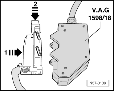
‒ → Fit test box V.A.G 1598/18 onto multi-pin connector (1) and lock, in direction of arrow (2).
Using test box V.A.G 1598/18 the wiring can be checked according to current flow diagram.
-
‒ Select the correct measuring range on tester before connecting the test leads. Otherwise the electronic components can be seriously damaged.
-
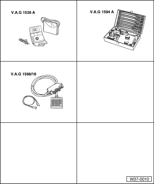
◆ Use hand multimeter V.A.G 1526 A with test leads from V.A.G 1594 for testing.
-
◆ The specified values are valid for an ambient temperature from 0 °C...40 °C.
-
◆ If the readings obtained differ from the specified values, determine fault on the basis of the current flow diagram.
-
◆ If the readings obtained differ only slightly from the specified values, clean sockets and connectors of the testers and test leads and repeat test. Before replacing the particular components, test wiring and connections and, particularly if specified values are below 10 ω, repeat resistance measurement on component.
|