audi Workshop Repair Guides

Audi Workshop Service and Repair Manuals

Enginecrankshaft group, pistons > < Installing
4-cyl. Diesel Direct Injection Engine (TDI), Mech. Components
Adjusting engine mountings
 
W00-0225

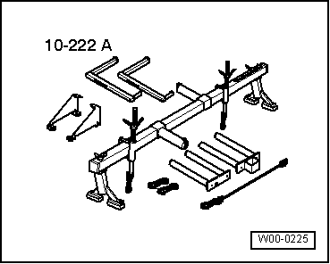
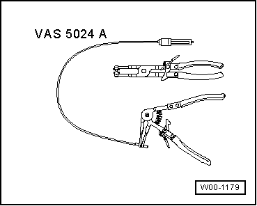
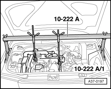
Special tools and workshop equipment required
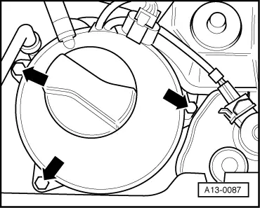
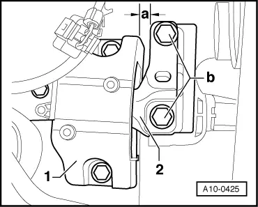
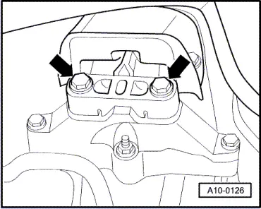
  • ◆ Support bar 10-222A

 
W00-1179
  • ◆ VAS 5024 A
 
A13-0087

Check adjustment

  • ‒ → Unscrew coolant expansion tank and refill reservoir for power steering -arrows-.

 
A13-0502
  • ‒ Detach the cover and the electrical connector at the right headlight unit.
  • ‒ → Disconnect fuel-feed line -2- and fuel-return line -1- at injection pump.
  • ‒ Disconnect the electrical connection -3- at the sender -G71/-G72.
  • ‒ Expose the wiring at the air duct pipe.
  • ‒ Remove the air duct pipe on right side -arrows-.
 
A10-0425
    • ‒ → Both bolt heads -b- must be flush with the edge of the support arm -2-.
    • ‒ Between engine console -1- and support arm -2- of the right engine mounting must be a distance a = 13 mm.
  • Use a 12 mm flat bar (if necessary, use special tool 2011) to check distance -a-. It must be easy to insert the flat bar.

 
A10-0933

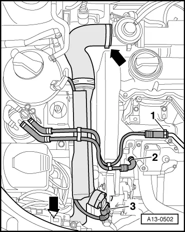
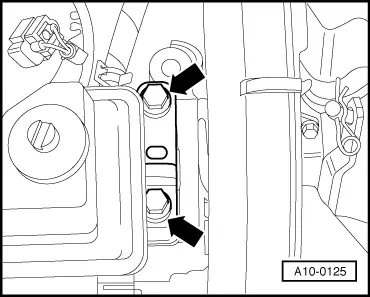
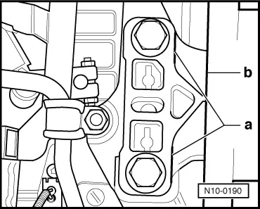
Adjusting

If the distance measured is too small or too large, proceed as follows:

  • ‒ → Remove air duct hose -1- from air duct pipe.
  • ‒ Detach connector of air mass meter -3-.
  • ‒ Unscrew bolts -4- and -5-.
  • ‒ Remove vent hose -2- from rear of air cleaner housing.
  • ‒ Take out air cleaner housing.
 
A37-0197
  • ‒ → Set up support bar 10-222 A on wing panel bolt flange.
  • ‒ Attach spindles in both lifting eyes.
  • ‒ Slightly lift engine using both spindles evenly.

 
A10-0125
  • ‒ → Loosen bolts -arrows- of assembly mounting on engine...
 
A10-0126
  • ‒ → ... and from gearbox. Replace all 4 bolts one by one (if not already done so when engine was installed) and hand-tighten.

 
A10-0425
  • ‒ → Loosen bolts -b- of support arms on left and right approx. two turns.
  • ‒ Using an tyre lever, displace engine between engine console -1- and support arm -2- until the distance on the engine side is a = 13 mm.
    • ‒ It must be easy to insert a 12 mm flat bar (or special tool 2011).
    • ‒ Both bolt heads -b- must be flush with the edge of the support arm.
  • ‒ Tighten the bolts -b- to 100 Nm on assembly mounting on engine side.
 
N10-0190
  • ‒ → Ensure that the edges on the load arm on the gearbox side -a- and gearbox console -b- are parallel.
  • ‒ Tighten the bolts to 100 Nmon assembly mounting on gearbox side.

The remaining installation steps are carried out in the reverse sequence:

Enginecrankshaft group, pistons > < Installing