audi Workshop Repair Guides

Audi Workshop Service and Repair Manuals

Stress free alignment of exhaust system > < Separating centre and rear silencers
4-cyl TDI®-Engine, Mechanical Components
Exhaust system -vehicles with four-wheel drive-
Removing and installing front exhaust pipe
 
W00-0120

Special tools and workshop equipment required

  • ◆ Engine/gearbox lifter V.A.G 1383 A

 
W00-0464
  • ◆ Hose clamp pliers V.A.G 1921
 
A10-0929

Removing

  • ‒ → Remove oil dipstick -1- from guide tube.
  • ‒ Remove engine cover -arrows-.
  • ‒ Reinsert dipstick in guide tube.

 
A13-0385
  • ‒ → Detach the crankcase vent pipe -6- from air duct pipe.
  • ‒ If installed, detach connector for heating resistor (crankcase venting) -N79 -Item 3-.
  • ‒ Set aside the vacuum hoses.
  • ‒ Unscrew bolts -1- and -2-.
 
A10-0458
  • ‒ Detach both front wheels.
  • ‒ → If installed, remove the headlight range control bracket in top right of wheel housing -arrows-.
  • ‒ Detach linkage for headlight range control from the wishbone and unplug connector.

 
A10-0930
  • ‒ → Remove air duct pipe from right longitudinal member -arrows-.
 
A37-0198
  • ‒ → Remove noise insulation in centre and on right -arrows-.

 
A10-1366
  • ‒ → Release spring clamp -arrow- at turbocharger using hose clamp pliers V.A.G 1921 or VAS 5024 A and disconnect the air duct pipe -1- from turbocharger.
  • ‒ Lift out the air duct pipe upwards.
 
A10-0933
  • ‒ → Unplug connectors for air mass meter -3-.
  • ‒ Unscrew bolts -4- and -5-.
  • ‒ Remove vent hose -2- off air cleaner housing.
  • ‒ Remove air cleaner housing.

 
A26-0622
  • ‒ → Unscrew nuts -2-, -4- and -5-.

Note:

The front exhaust pipe -1- remains connected to the turbocharger -3-.

 
A26-0621

Note:

The isolating element in front exhaust pipe must not be deflected more than 10°to avoid damage.

  • ‒ → Remove bolts -arrows- at the front exhaust pipe/catalytic converter flange.

 
V26-0733
  • ‒ → Detach the exhaust system at the clamping sleeve -arrows-.
  • ‒ Remove catalytic converter.
 
A26-0431
  • ‒ → Unbolt bracket for exhaust system from assembly mounting
    -arrows-.

 
N34-0887
  • ‒ → Unscrew pendulum support from subframe -arrows A-.
 
A40-0239
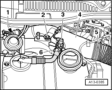
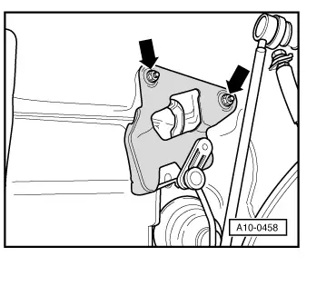
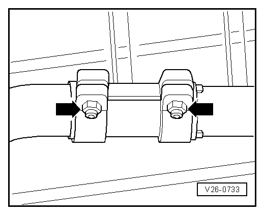
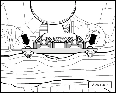
  • ‒ → Remove bolts -2- and detach pendulum support.
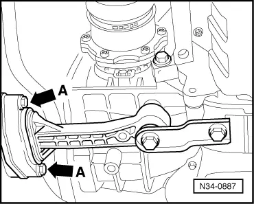
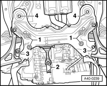
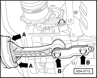
  • ‒ Remove bolts -1- for steering box.
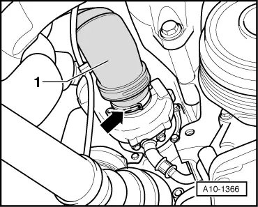
  • ‒ Lever steering box off subframe (dowel sleeve) and detach power-steering pressure line at subframe.
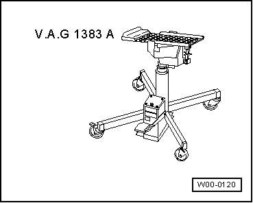
  • ‒ Position gearbox lifter V.A.G 1383 A with universal mount 1359/2 underneath subframe.
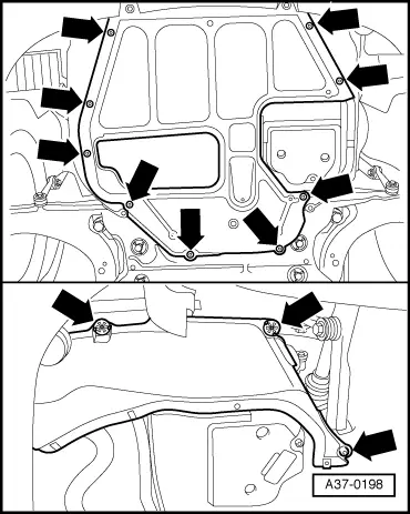
  • ‒ Unscrew bolts -3- and -4- for subframe.
  • ‒ Carefully lower subframe, leave attached at the wishbones and connecting rods, while pressing steering box upwards.
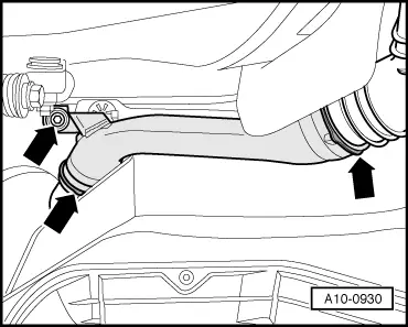
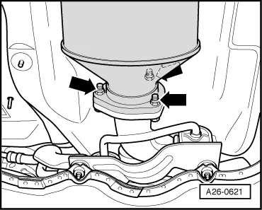
  • ‒ Remove front exhaust pipe.

Installing

Installation is carried out in the reverse order; note the following:

Note:

Always replace seals, gaskets and self-locking nuts.

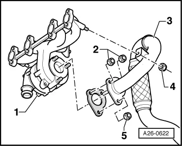
  • ‒ Fit front exhaust pipe to turbocharger and secure with nut.
  • ‒ Installing subframe

=> Running Gear, FWD and 4WD; Repair group 40

 
N34-0712
  • ‒ → First attach pendulum support to gearbox -arrows B- and then to subframe -arrows A-.
  • ‒ Only use new bolts to secure.
  • ‒ Install catalytic converter.
  • ‒ Stress-free alignment of exhaust system => Page 26-35
 
N21-0184
  • ‒ → When installing air duct pipes with connectors, ensure that the securing clip -arrow- engages audibly in the retaining lug -A-.

Tightening torques

Component

Nm

Bracket for exhaust system to subframe

23

Pendulum support to gearbox

40 + 90° 1)2)

Pendulum support to subframe

20 + 90°1)2)

Catalytic converter to front exhaust pipe

23 3)

Front exhaust pipe on turbocharger

253)

    1)    Stretch bolts, replace

    2)    90°corresponds to a quarter of a turn

    3)    Replace the nuts.

Stress free alignment of exhaust system > < Separating centre and rear silencers