audi Workshop Repair Guides

Audi Workshop Service and Repair Manuals

Adjusting assembly mountings > < Securing engine to assembly stand
Installing engine
Installing engine
Special tools and workshop equipment required
t  Depth gauge for vehicles with automatic gearbox
Procedure
  Note
t  On assembly, renew oil seals and gaskets as well as self-locking nuts and bolts that are tightened by turning through to a specified angle.
t  Hose connections and hoses for charge air system must be free of oil and grease before assembly.
t  Fit all heat insulation sleeves in the original position when installing.
t  Secure all hose connections with the correct type of hose clips (same as original equipment) → Parts catalogue.
t  Fit all cable ties in the original positions when installing.
–  Check whether dowel sleeves for centring the engine/gearbox assembly are fitted in the cylinder block; install dowel sleeves if necessary.
   
–  Engage intermediate plate on sealing flange and slip onto dowel sleeves -arrows-.
Vehicles with manual gearbox:
–  Check that clutch plate is correctly centred.
–  Check clutch release bearing for wear, renew if necessary.
–  Lightly grease clutch release bearing, release bearing guide sleeve and splines on input shaft with grease for clutch plate splines -G 000 100-.
–  Bolt gearbox onto engine. Use new securing bolts on vehicles with manual gearbox 02M.
  Note
t  Tightening torques apply only to lightly greased, oiled, phosphated or black-finished nuts and bolts.
t  Additional lubricant such as engine oil or gearbox oil may be used, but do not use lubricant containing graphite.
t  Do not use degreased parts.
t  Tolerance for tightening torques ± 15 %.
  A10-0129
Securing engine to manual gearbox 02J
  A37-0214
ItemBoltNm
1, 2 1), 8M12x5580
3 1), 4M12x15080
5, 7M10x5045
6M10x7045
ADowel sleeves for centralising
l  1) Bolt with M8 stud

   
Securing engine to manual gearbox 02M
  A37-0214
ItemBolt 2Nm
1, 2 1)M12x5580
3 1), 4 1)M12x16580
5M10x10540
6, 7M10x5040
8M12x7080
ADowel sleeves for centralising
l  1) Bolt with M8 stud
l  2) Renew bolts.

   
–  Push in small cover plate -2- for flywheel in such a way that lug at bottom engages into the cylinder block and secure with bolt -1-.
  Note
Shown in illustration with gearbox removed.
  A34-0234
Vehicles with four-wheel drive:
–  Fit bolts -A ... C- of bevel box bracket. Note tightening sequence:
  V34-3004
1.  Tighten bolts -B- and -C- initially to 10 Nm.
2.  Tighten bolts -A- to 25 Nm.
3.  Tighten bolts -B- and -C- to 40 Nm.

   
Vehicles with automatic gearbox:
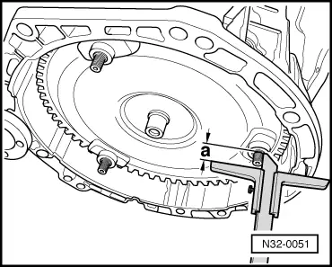
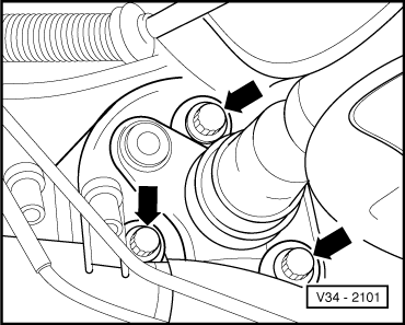
If the torque converter is correctly installed, the depth -a- between the contact surfaces at the bottom of the studs on the torque converter and the contact surface of the torque converter bell housing is about 22 mm.
If the torque converter has not been completely inserted, this distance will be approx. 10 mm.
  Caution
If the torque converter is not installed correctly, the drive lugs of the torque converter and the ATF pump will be seriously damaged when the gearbox is joined to the engine.
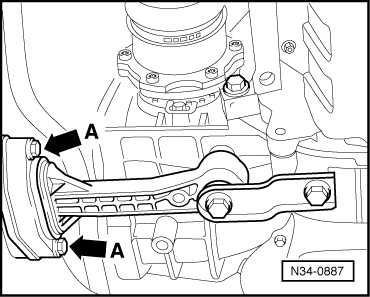
–  To secure torque converter on drive plate, use only genuine nuts (same as original equipment) as specified in → Parts catalogue.
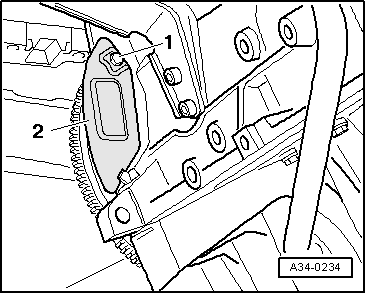
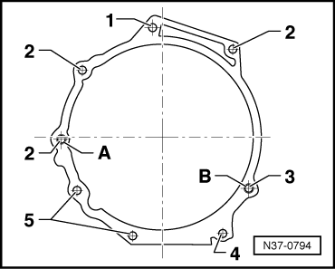
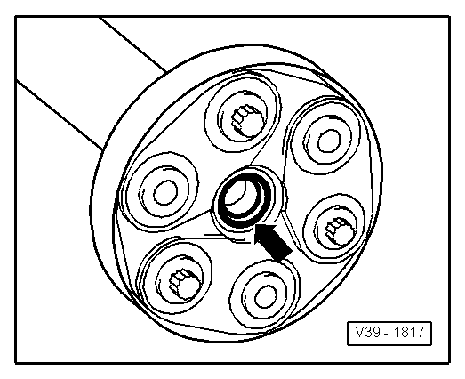
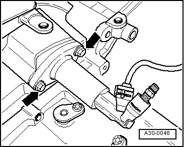
–  Before installing engine, rotate torque converter and drive plate so that one hole and one stud are level with the aperture for the starter motor.
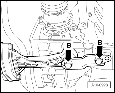
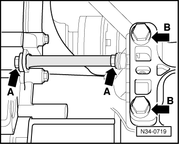
–  Bolt gearbox to engine.
  Note
t  Tightening torques apply only to lightly greased, oiled, phosphated or black-finished nuts and bolts.
t  Additional lubricant such as engine oil or gearbox oil may be used, but do not use lubricant containing graphite.
t  Do not use degreased parts.
t  Tolerance for tightening torques ± 15 %.
  N32-0051
Securing engine to automatic gearbox 01M
  A37-0214
ItemBoltNm
1, 2M12x6580
3, 4 1)M12x18080
5 … 7M10x5045
8M12x8080
ADowel sleeves for centralising

   
Securing engine to automatic gearbox 09A
  N37-0794
ItemBoltNm
1M12x4080
2 1)M12x6080
3M12x7080
4M10x7045
5M10x5545
A, BDowel sleeves for centralising
l  1) Bolts on left of illustration with M8 stud.

   
All models:
–  Tighten bolts securing engine mounting to engine support -arrows- initially hand-tight.
  A10-0125
–  Guide engine/gearbox assembly into the body.
–  Use new bolts for securing.
  Note
The bolts are tightened to final torque only after adjusting the engine mountings → Chapter.
–  Remove engine bracket -T10012- from engine.
–  Bolt drive shafts to flange shafts of gearbox → Rep. Gr.40.
  Note
Drive shafts must be installed prior to further assembly.
  A10-0126
–  Secure pendulum support at gearbox -arrows B-.
–  Use new bolts for securing.
  A10-0928
Vehicles with four-wheel drive:
–  Secure front exhaust pipe to turbocharger.
  Caution
Avoid damaging the seal -arrow- in the propshaft flange when installing. If a seal is damaged the propshaft must be renewed.
–  Push engine/gearbox assembly towards bulkhead; the journal of the bevel box must be simultaneously inserted horizontally and carefully into the flange of the propshaft.
  V39-1817
All models:
–  Secure pendulum support to subframe -arrows A-.
–  Use new bolts for securing.
  N34-0887
Vehicles with four-wheel drive:
–  Secure propshaft with flexible coupling to bevel box -arrows- → Rep. Gr.39.
All models:
–  Install exhaust system and align it free of stress → Chapter or → Chapter.
–  Knock back bushes for securing bolts slightly to facilitate installation of power steering pump and air conditioner compressor.
–  Install power steering pump → Rep. Gr.48.
–  Install secondary air pump → Chapter.
–  Install air conditioner compressor → Rep. Gr.87.
  V34-2101
Vehicles with manual gearbox:
  Caution
The clutch pedal must not be operated before installing slave cylinder.
–  Install clutch slave cylinder -arrows- → Rep. Gr.30.
  A30-0048
–  Install gearbox strut -arrows A-.
–  Install cable support bracket and selector cables → Rep. Gr.34.
–  Adjust selector cables → Rep. Gr.34.
All models:
Remaining installation steps are carried out in reverse sequence; note the following:
–  Install poly V-belt → Chapter.
–  Adjust assembly mountings → Chapter.
Vehicles with throttle cable:
–  Adjust throttle cable → Rep. Gr.20.
All models:
–  Connect vacuum hoses → Chapter.
–  Electrical connections and routing → Current flow diagrams, Electrical fault finding and Fitting locations.
Vehicles from model year 2001 onwards:
–  Install washer fluid reservoir → Rep. Gr.94.
All models:
  Note
t  When the battery is reconnected, please ensure that the vehicle equipment (e.g. radio, radio/navigation system, clock, electric window lifters) is activated as described in the operating instructions.
t  For further operations after reconnecting power supply, refer to → Rep. Gr.24.
–  Install and adjust wiper arms → Rep. Gr.92.
–  Check oil level → Chapter.
–  Fill cooling system → Anchor.
  Note
t  Drained-off coolant may only be used again if the original cylinder head and cylinder block are re-installed.
t  Contaminated or dirty coolant must not be used again.
  WARNING
Never use battery charging equipment for boost starting. There is danger of damaging the vehicle's control units.
Tightening torques
  N34-0719
ComponentNm
Bolts/nutsM610
M820
M1045
M1265
Except for the following: 
Torque converter to drive plate57
Front exhaust pipe to turbocharger40
Radiator cowl to radiator10
Pendulum support to:Gearbox40 + 90° 1)2)
Subframe20 + 90° 1)2)
Catalytic converter to front exhaust pipe40
Drive shaft heat shield to cylinder block35
Gearbox strut25
Hose clips for coolant hoses2
Hose clips for air hoses3.5
l  1) Renew bolts.
l  2) 90° = one quarter turn.


Adjusting assembly mountings > < Securing engine to assembly stand