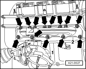
| Component | Nm |
| Exhaust manifold to cylinder head | 30 1) |
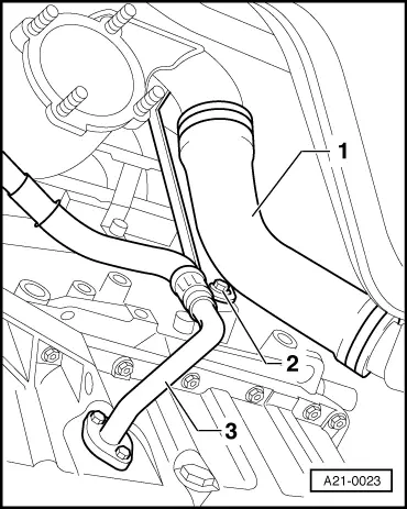
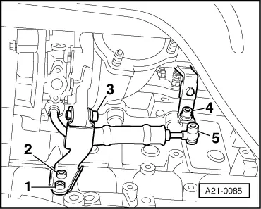
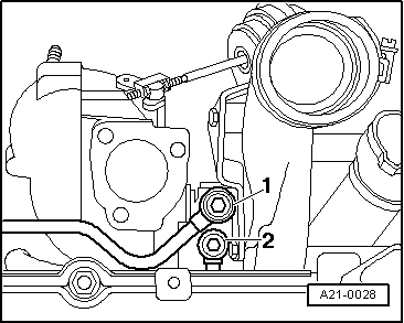
| Coolant supply pipe to: | Turbocharger | 35 |
| Cylinder block | 35 |
| Coolant return pipe to turbocharger | 35 |
| Bracket for coolant return pipe to cylinder block | 23 |
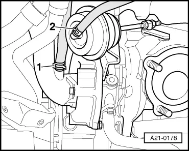
| Oil supply pipe to turbocharger | 30 |
| Bracket for coolant supply pipe to turbocharger | 10 |
| Turbocharger to exhaust manifold | 35 2)3) |
| Bracket for turbocharger to: | Cylinder block | 25 |
| Turbocharger | 45 |
| Retainer for oil supply pipe to cylinder head | 10 |
| Heat shield to cylinder head | 23 |
| Oil return pipe to: | Sump | 10 |
| Turbocharger | 10 |
| Front exhaust pipe with catalytic converter to turbocharger | 40 |
| Drive shaft heat shield to cylinder block | 35 |
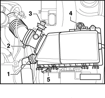
| Hose clips for air hoses | 3.5 |
| l
| 3) Coat threads and contact surface of bolt heads with high-temperature paste; for high-temperature paste refer to → Parts catalogue. |
|

 Note
Note
 WARNING