audi Workshop Repair Guides

Audi Workshop Service and Repair Manuals

Enginecrankshaft group, pistons > < Installing
4-cylinder Engine (2-valve), Mechanical Components
Adjusting engine mounting
 
W00-0225

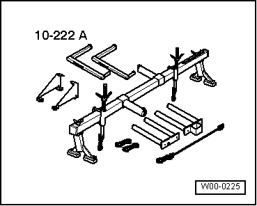
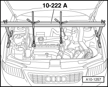
Special tools and workshop equipment required
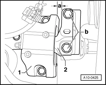
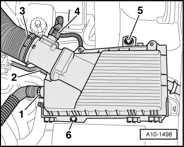
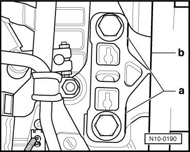
  • ◆ Support bar 10-222A

 
A10-1490

Checking adjustment

  • ‒ → Remove engine covers -arrows-.

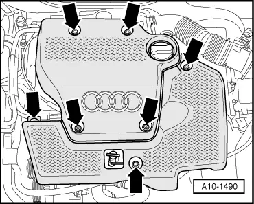
Note:

Fig. shows bolted engine cover.

 
A13-0435
  • ‒ → Detach the coolant expansion tank -1- and refill reservoir -2- for power steering. Do not detach hoses.

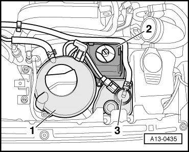
Note:

The ACF -3- remains installed.

 
A10-0425
    • ‒ → Both bolt heads -b- must be flush with the edge of the support arm -2-.
    • ‒ Between engine console -1- and support arm -2- of the right engine mounting must be a distance a = 13 mm.
  • Use a 12 mm flat bar (if necessary, use special tool 2011) to check distance -a-. It must be easy to insert the flat bar.
 
A10-1498

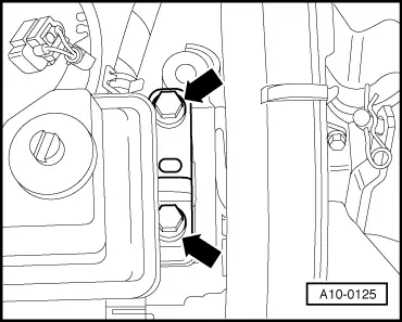
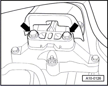
If the distance measured is too small or great, proceed as follows:

  • ‒ → Disconnect the air duct hose -3- from the air mass meter.
  • ‒ Unplug connector -4- at air mass meter.
  • ‒ Where fitted, disconnect vacuum hoses -1- and -2- at air cleaner housing.
  • ‒ Unscrew bolts -5- and -6-.
  • ‒ Remove air cleaner housing.

 
A10-1257

Note:

Push a plastic or wooden support between the wing mounting flange and side panel in order to prevent deformation of the wing.

  • ‒ → Set up support bar 10-222 A in front of gas pressure spring onto wing bolt edge. Spindles are at the front.
  • ‒ Attach the snap hooks of the spindles to the lifting eye or bracket T10013.
  • ‒ Lift engine with both spindles evenly and slightly.
 
A10-0125
  • ‒ → Loosen bolts -arrows- of assembly mounting on engine...

 
A10-0126
  • ‒ → ...and from gearbox. Replace all 4 bolts one by one (if not already replaced when engine was installed) and hand-tighten them.
 
A10-0425
  • ‒ → Loosen bolts -b- of support arms on left and right approx. two turns.
  • ‒ Using an assembly iron displace engine between engine console -1- and support arm -2- until the distance on engine side is a = 13 mm.
    • ‒ It must be easy to insert a 12 mm flat bar (or special tool 2011).
    • ‒ Both bolt heads -b- must be flush with the edge of the support arm.
  • ‒ Tighten bolts -b- for mechanical unit bracket on engine side 60 Nm + 90°.

 
N10-0190
  • ‒ → Ensure that the edges on the load arm on the gearbox side -a- and gearbox console -b- are parallel.
  • ‒ Tighten bolts -b- for mechanical unit bracket on gearbox side to 60 Nm + 90°.

The remaining installation steps are carried out in the reverse sequence:

Enginecrankshaft group, pistons > < Installing