audi Workshop Repair Guides

Audi Workshop Service and Repair Manuals

Detaching engine from gearbox > < Removing - vehicles with engine codes AEH, AKL
4-cylinder Engine (2-valve), Mechanical Components
Removing and installing engine
Removing - vehicles with engine code APF

Notes:

  • ◆ The engine is removed from underneath together with the gearbox.
  • ◆ Replace all cut and defective cable ties. Refit cable ties in the same position when installing the engine.
  • ◆ Collect drained coolant in a clean container for re use or disposal.
Important
On vehicles with telematics, activate service mode of telematics control unit before disconnecting battery.=>Radio, Telephone and Navigation System; Repair group 91
  • ‒ Refer to coding on vehicles with encoded radio/radio navigation system (RNS); if necessary, interrogate.
  • ‒ Disconnect earth strap at battery with ignition switched off.
 
A10-0885
Important
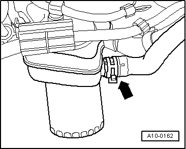
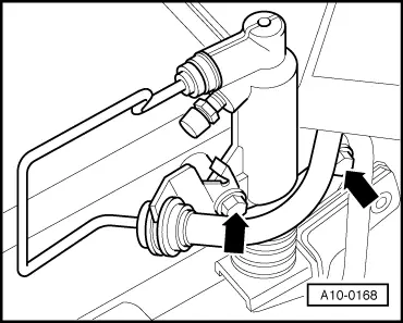
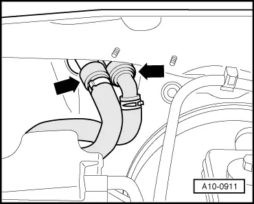
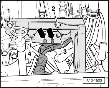
Hot steam or hot coolant can escape when opening expansion tank. Cover cap with a cloth and open carefully.
  • ‒ Open the cover of the coolant expansion tank
  • ‒ → Remove engine cover -arrows-.

 
A10-0161
  • ‒ → Remove noise insulation from centre, left and right sides -arrows-
 
A17-0215
  • ‒ → Detach connector from oil level sender -arrow-.
  • ‒ Move wiring to the top.

 
A19-0276
  • ‒ Place drip tray V.A.G 1306 below engine.

Vehicles with drain plug:

  • ‒ → Turn drain plug -1- on radiator anti-clockwise, fit auxiliary hose to connection if necessary.

All models:

  • ‒ Pull off retaining clip -2- for bottom coolant hose and detach coolant hose from radiator.
 
A10-0162
  • ‒ → Also disconnect lower coolant hose on oil cooler -arrow-, and drain off remaining coolant.

 
A10-1498
  • ‒ → Disconnect the air duct hose -3- from the air mass meter.
  • ‒ Unplug connector -4- at air mass meter.
  • ‒ Disconnect hoses -1- and -2- from the air cleaner housing.
  • ‒ Unscrew bolts -5- and -6-.
  • ‒ Remove air cleaner housing.
 
A10-1492
  • ‒ → Disconnect hoses -1- and -3-.
  • ‒ Remove air duct, release spring clamp -2- for this purpose.

 
A10-0912
  • ‒ Open cover of main fuse box towards front.
  • ‒ → Unclip protective cover -2- for electrical cables.
  • ‒ Unscrew black electric cable -1- from fuse bar.
  • ‒ Remove the battery.
 
A10-0116
  • ‒ → Remove battery carrier -arrows-.

 
A10-0167

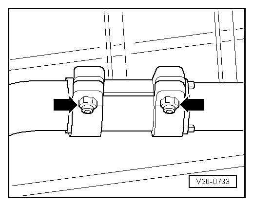
Vehicles with manual gearbox:

  • ‒ → Press off selector rods -1- and -2- with a screwdriver.
  • ‒ Detach shift mechanism from gearbox -arrows- and suspend.
 
A10-0168
  • ‒ → Detach slave cylinder -arrows - and move clear to one side. Secure slave cylinder in position with wire; do not open hydraulic connections.
Important
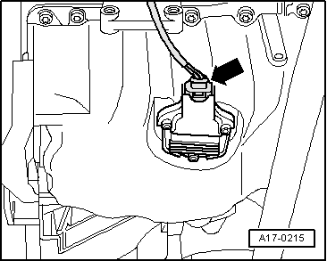
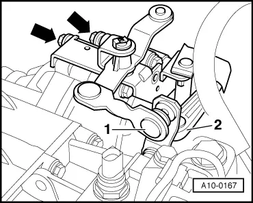
Do not depress clutch pedal after removing slave cylinder.

 
A34-0054
  • ‒ → Unplug the connector -arrow 1- at speedometer sender -G22.
  • ‒ Unplug the connector -arrow 2- for the reversing light switch.
  • ‒ Lay wiring aside.
 
A37-0194

Vehicles with automatic gearbox:

  • ‒ → Press off selector lever cable -1- with screwdriver at gearbox selector lever -4- detach securing clip -3- from support bracket.
  • ‒ Detach selector cable and move to one side.

 
A37-0193
  • ‒ → Disconnect electrical connectors:
  •     1 -    To solenoid valves (10-pin connector)
  •     2 -    To road speed sender -G68
  •     3 -    At multi-function switch -F125
  •     4 -    At gearbox speed sender -G38
  • ‒ Lay wiring harness aside.

All models:

  • ‒ Unbolt bracket for power steering pressure line from rear of gearbox support.
 
A37-0195
  • ‒ → Unscrew earth wiring -1- from flange engine/gearbox.
  • ‒ Disconnect leads -3- and -4- to the starter.
  • ‒ Unplug connector -2- and pull out of bracket.
  • ‒ Disengage wires from bracket on starter, move wires to one side and detach bracket.

 
A10-1499
  • ‒ → Unplug the connectors at the throttle valve body -1- and at the exhaust gas recirculation valve -2-.
  • ‒ Lay wiring aside.
  • ‒ Detach hose -3- from combination valve for secondary air inlet.
 
A10-1500
  • ‒ → Disconnect the coolant hose -arrow- to the coolant compensation tank at the T-union.

 
A10-0911
  • ‒ → Detach refrigerant hoses to radiator heat exchanger on bulkhead -arrows-.
 
A10-1501
  • ‒ → Disconnect the coolant hose -1- from the coolant distributor housing.
  • ‒ Unplug the connectors at the coolant temperature sender -G62 -Item 2- and at the thermostat for map-controlled engine cooling -3-.

 
A10-1494
  • ‒ → Disconnect the vacuum hose -arrow- to the brake servo at the intake manifold.
 
A10-1502
  • ‒ → Detach connector -1-.
  • ‒ Disconnect hoses -2- and -3- at the secondary air pump.
  • ‒ Detach the secondary air pump -4- from the bracket.

 
A10-1503
  • ‒ → Unscrew bolts -1...4- of the secondary air pump bracket.
  • ‒ Lay the wiring aside -arrow- and remove the secondary air pump bracket.
 
A10-1504
  • ‒ → Disconnect electrical connectors:
  •     1 -    Knock sensor -G61
  •     2 -    Engine speed sender -G28
  •     3 -    Ignition coils -N and -N128 with output stage -N122
  •     4 -    Oil pressure switch -F1 (on oil filter bracket)
  •      -    Oil temperature sender -G8 (on oil filter bracket)
  • ‒ Lay wiring aside.

 
A10-0114
  • ‒ → Detach connector -2-.
  • ‒ Unscrew wire -1- from alternator.
  • ‒ Unscrew the cable clamp -3- and lay wiring aside.
 
A10-0164
  • ‒ → Disconnect electrical connectors:
  •     1 -    Intake manifold change-over valve -N156
  •     2 -    Hall sender -G40
  •     3 -    Injectors -N30, -N31, -N32, -N33
  • ‒ Lay wiring aside.

 
A10-0977
  • ‒ → Detach coolant hose between engine and radiator -arrows-.
 
A10-0891
  • ‒ → Remove coolant hose -2- and set aside.
  • ‒ Unplug connector -1- for solenoid clutch on air conditioner compressor.
  • ‒ Move wiring harness aside.

 
A13-0083

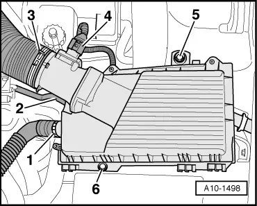
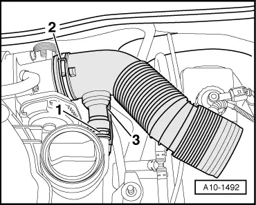
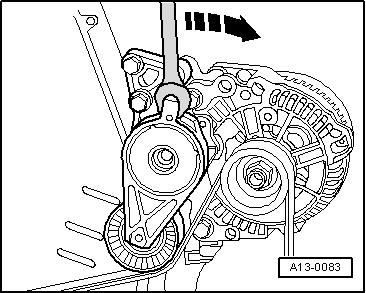
Note:

Mark the running direction with chalk or a felt-tipped pen before removing the ribbed belt. If the belt runs in the opposite direction when it is refitted, this can cause breakage.
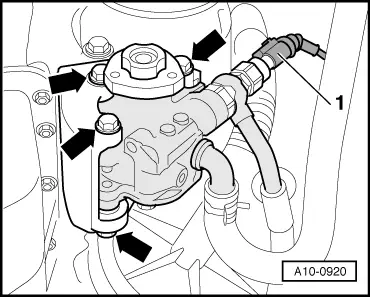
  • ‒ → To loosen ribbed belt, turn tensioner in direction of arrow.
 
N13-0620
  • ‒ → Lock the ribbed belt tensioner with mandrel T10060 or with an angled Allen key.
  • ‒ Remove ribbed belt.

 
A10-0169
Important
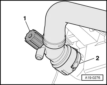
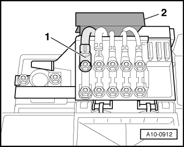
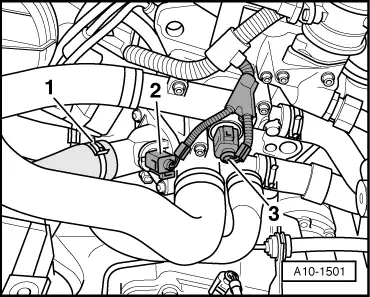
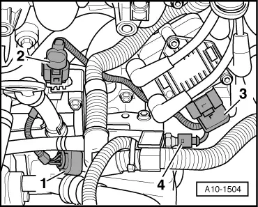
The fuel system is pressurised. Before opening the system place a cloth around the connection point. Then release pressure by carefully loosening the connection.
  • ‒ → Mark fuel feed pipe -1- and fuel return pipe -2- and disconnect (press release tab).
  • ‒ Disconnect hose -3- from ACF container.
 
A10-0125
  • ‒ → Loosen bolts -arrows- of assembly mounting on engine...

 
A10-0126
  • ‒ → ...and on gearbox approx. 2 turns.
  • ‒ Unscrew bolts accessible from above securing bolts for radiator cowl.
 
A10-1496
  • ‒ → Disconnect power steering line from gearbox -arrow-.

 
A10-0920
  • ‒ → Detach electrical connection from -1- pressure switch/power steering -F88.
  • ‒ Lay wiring aside.
  • ‒ Detach pulley of power steering vane pump; counterhold with drift.
  • ‒ Detach vane pump for power steering -arrows-. Do not detach hydraulic connections.
 
A10-0415
  • ‒ → Detach both connectors for left radiator fan on bottom of radiator cowl.
  • ‒ Unscrew bolts accessible from below on radiator cowl.
  • ‒ Remove the radiator cowl with both vents from below.
  • ‒ Suspend vane pump for power steering together with line from lock carrier.

 
A10-0941

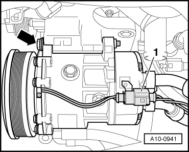
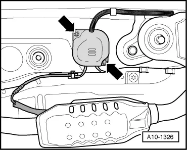
Vehicles with air conditioner:

Important
The air conditioner refrigerant circuit must not be opened.
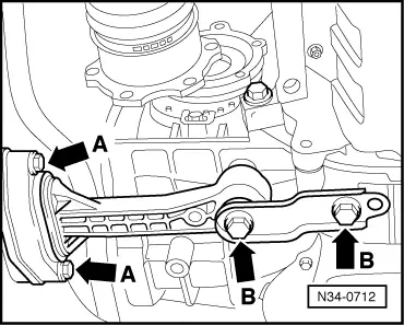
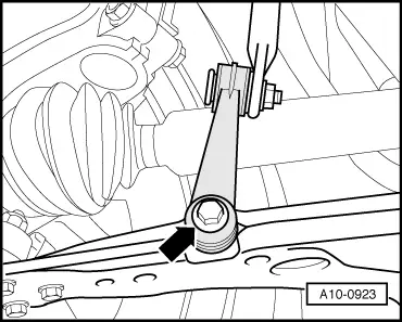
  • ‒ → Remove bolts -arrow- for air conditioner compressor.
  • ‒ Suspend the air conditioner compressor together with the connected refrigerant hoses from the bonnet lock.
 
A10-1326

All models:

  • ‒ → Unscrew protective cover -arrows- on vehicle floor.
  • ‒ Unplug connector for lambda probes and lay wiring aside.

 
A10-0921
  • ‒ → Unbolt heat shield for right drive shaft -arrows-.
 
A10-0970

Note:

The isolating element in front exhaust pipe must not be deflected more than 10°to avoid damage.

  • ‒ → Remove securing bolts -arrows- of front exhaust pipe/exhaust manifold.

 
V26-0733
  • ‒ → Detach the exhaust system at the clamping sleeve -arrows-.
  • ‒ Detach the front exhaust pipe, swivel the front exhaust pipe 180° for this purpose.
 
N34-0712
  • ‒ → First remove bolts -A- and then bolts -B- from pendulum support.
  • ‒ Detach pendulum support.

 
A10-0923
  • ‒ → Unbolt right connecting link from wishbone -arrows-.
  • ‒ Unscrew drive shaft on left and right from gearbox flange.
  • ‒ Turn front wheels to the right.
  • ‒ Push engine forward and at the same time swivel right drive shaft towards front.
 
A02-0069
  • ‒ → Pull release tabs -arrows- and remove air intake grille.
  • ‒ Suspend right drive shaft at towing eye -1- using a wire loop.

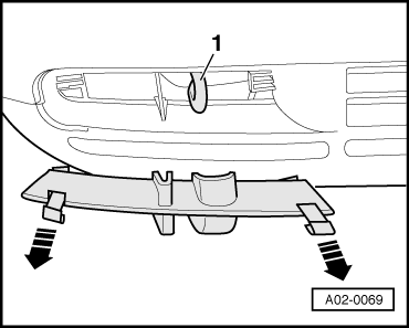
Note:

Protect bumper from scratches by using an adhesive tape.

  • ‒ Move left drive shaft towards rear and attach to anti-roll bar using a wire loop.

 
N10-0056
  • ‒ → Attach engine mounting T10012 with securing nut and bolt with approx. 20 Nm to cylinder block.
  • ‒ Insert engine/gearbox lifter V.A.G 1383 A in engine mounting T10012 and raise slightly.

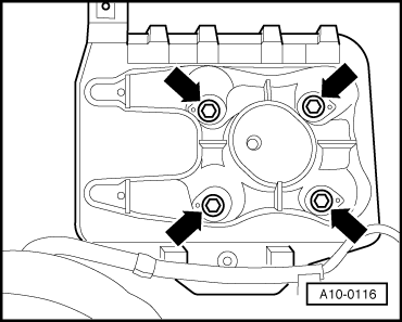
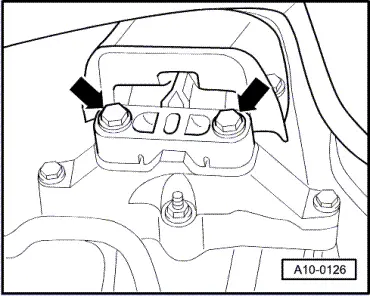
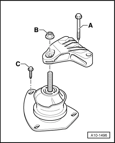
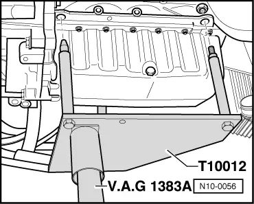
Note:

To unscrew bolts for assembly mounting use stepladder VAS 5085.

 
A10-0125
  • ‒ → Loosen bolts -arrows- of assembly mounting on engine...

 
A10-0126
  • ‒ → ...and from gearbox.

Notes:

  • ◆ Check that all hoses and wiring connections between engine, gearbox and body have been detached.
  • ◆ Carefully guide engine/gearbox assembly when lowering to avoid damage.
  • ‒ Pull engine/gearbox assembly as far forward as possible, and lower gradually.

Detaching engine from gearbox > < Removing - vehicles with engine codes AEH, AKL