audi Workshop Repair Guides

Audi Workshop Service and Repair Manuals

Disassembling and assembling coolant distributor housing > < Performing diagnosis of the map-controlled engine cooling system
4-cylinder Engine (2-valve), Mechanical Components
Removing and installing cooling system components - vehicles with engine code APF
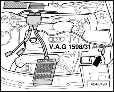
Performing electrical check of map-controlled engine cooling system
 
G24-0020

Special tools and workshop equipment required

  • ◆ V.A.G 1526 A
  • ◆ V.A.G 1594 A
  • ◆ V.A.G 1598/31
Important
The motors for the radiator fan may start up.

Test requirements:

  • ● Diagnosis of map-controlled engine cooling system performed .
 
A10-0885

Test sequence

  • ‒ → Remove engine cover -arrows-.
  • ‒ Start engine and run at idling speed.
 
A26-0315
  • ‒ → Unplug 4-pin connector -1- at coolant temperature sender -G62.

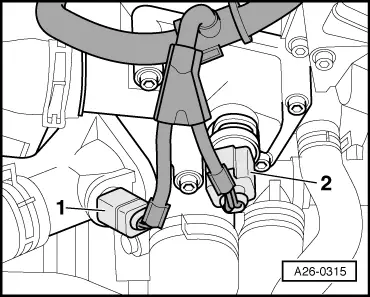
Note:

Unplugging the connector from the coolant temperature sender causes the engine control unit to detect a fault in the map-controlled engine cooling system. It then constantly actuates the thermostat using full battery voltage.

  • ‒ Unplug the 2-pin connector -2- from thermostat for map-controlled engine cooling system -F265.

 
A24-0331
  • ‒ → Connect multimeter between contacts 1 and 2 to measure voltage.
    • ‒ Specification: Approx. battery voltage (after a short waiting period)

If specification is not attained:

  • ‒ Connect multimeter as follows to measure voltage:

Connector
Contact

Measure to

1

Engine earth

    • ‒ Specification: approx. battery voltage
  • Switch ignition off.

If specification is not attained:

  • ‒ Check the wiring from contact 1 of the connector to the power supply relay for Simos control unit -J363 (below cover on left of bulkhead) for open circuit using the current flow diagram.
  • ‒ Eliminate open circuit or using the current flow diagram.
 
A24-0198

If specification is attained:

  • ‒ → Connect the V.A.G 1598/31 test box to wiring harness connectors; the engine control unit should not be connected. Attach the earth clip of test box to earth -arrow-.

=> Simos Fuel Injection and Ignition System; Repair group 24

Important
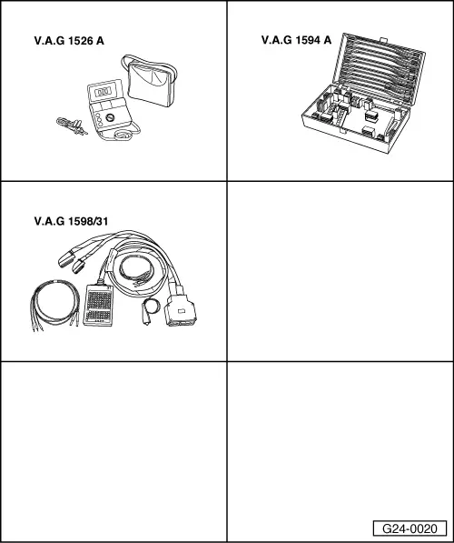
To prevent damage to the electronic components, select appropriate measuring range before connecting the measuring cables and observe the test requirements.

 
A24-0331
  • ‒ → Check for open circuit in the following wiring connections:

Connector
Contact

Test box V.A.G 1598/31
Socket

2

116

  • ‒ Eliminate open circuit using the current flow diagram.

If no wiring fault is detected:

  • ‒ Check function of thermostat => Page 19-36.
  • ‒ Plug in the connectors.
  • ‒ Finally, interrogate and erase the engine control unit fault memory as faults are stored when the connectors are unplugged.

=> Simos Fuel Injection and Ignition System; Repair group 24

Disassembling and assembling coolant distributor housing > < Performing diagnosis of the map-controlled engine cooling system