audi Workshop Repair Guides

Audi Workshop Service and Repair Manuals

Removing and installing complete toothed belt > < Removing and installing bracket for auxiliary assemblies
4-cylinder Engine (2-valve), Mechanical Components
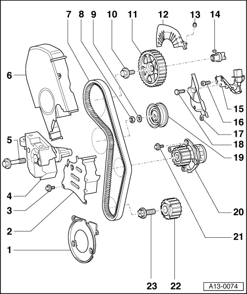
Dismantling and assembling engine
Removing and installing toothed belt
 
A13-0074

Note:

Mark the running direction with chalk or felt pen before removing the toothed belt. If the belt runs in the opposite direction when it is refitted, this can cause breakage.

  • Toothed belt guard - lower
    • ◆ Detach to remove crankshaft pulley
  • Toothed belt guard - centre
  • 10 Nm
    • ◆ Install using locking compound
    • ◆ Locking compound

=> Parts List

 
A13-0074
  • Removing
    • ◆ Engine support => Removing and installing toothed belt, Page 13-25
  • 45 Nm
    • ◆ Observe the tightening sequence
  • Toothed belt guard - upper
    • ◆ When installing, engage carefully in centre toothed belt guard.
  • Toothed belts
    • ◆ Mark running direction with chalk or felt pen before removing
    • ◆ Check for wear
    • ◆ Removing
    • ◆ Install (adjust valve timing) => Page 13-30.
  • 20 Nm
 
A13-0074
  • Corrugated washer
  • 100 Nm
    • ◆ To loosen and tighten, use counterhold 3415 =>Fig.1
  • Camshaft sprocket
    • ◆ With sender wheel for Hall sender -G40
    • ◆ For removal and installation remove toothed belt => Page 13-25
    • ◆ Installation position is fixed by Woodruff key -Item 14-
  • Toothed belt guard - upper
    • ◆ When installing, engage carefully in centre toothed belt guard.
  • 10 Nm
 
A13-0074
  • Woodruff key
    • ◆ Ensure tight fit
  • Hall sender -G40
    • ◆ Make sure base plate is properly centred when installing
  • 10 Nm
  • Toothed belt guard - rear
  • 20 Nm
  • Tensioning roller (semi-automatic)
    • ◆ Checking => Page 13-44
    • ◆ Installation position => Fig. 2.
  • Coolant pump
    • ◆ Removing and installing
      .
 
A13-0074
  • 15 Nm
  • Crankshaft sprocket
    • ◆ Contact surface between sprocket and crankshaft must be free of oil
    • ◆ Can only be installed in one position
  • 90 Nm + 90° (1/4 turn) further
    • ◆ Replace
    • ◆ Do not use oil
    • ◆ Counter hold with 3415 to loosen and tighten
    • ◆ Bolt on counterhold 3415 => Fig.13-24
 
N15-0209

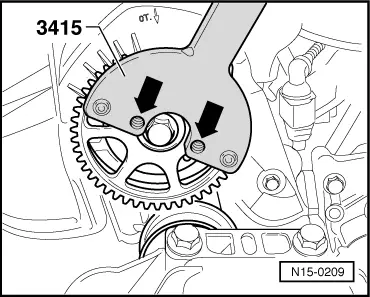
→ Fig.1    Detaching camshaft sprocket

  • ‒ Use counterhold tool 3415 to loosen and tighten the central bolt.

Note:

Remove the bolts from the threaded bores -arrows- before applying counterhold 3415.

 
A13-0078

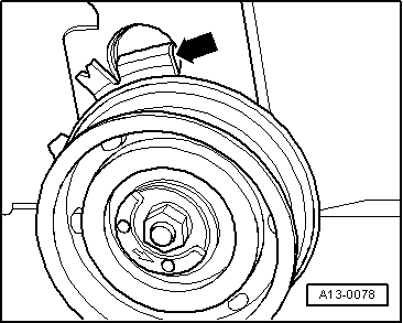
→ Fig.2    Installation position of semi-automatic tensioning roller

Retaining lug -arrow- must engage in slot on cylinder head.

 
A13-0338

→ Fig.3    Removing and installing crankshaft sprocket

  • ‒ Use counterhold 3415 to loosen and tighten the central bolt.

 
A13-0505

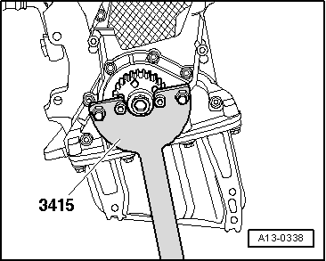
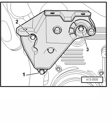
→ Fig.4    Installing engine support

  • ‒ Remove bolts -1...3-.
  • ‒ Then tighten the bolts -1...3- to 45 Nm.

Removing and installing complete toothed belt > < Removing and installing bracket for auxiliary assemblies