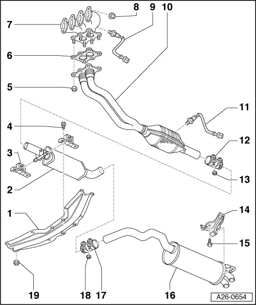
audi Workshop Repair Guides

Audi Workshop Service and Repair Manuals

Separating centre and rear silencers > < Checking cooling system for leaks
4-cylinder Engine (2-valve), Mechanical Components
Removing and installing parts of exhaust system

Notes:

  • ◆ Always replace seals, gaskets and self-locking nuts.
  • ◆ After working on the exhaust system ensure that the system is not under stress, and that it has sufficient clearance from the body. If necessary, loosen clamping sleeve and align silencers and exhaust pipe so that sufficient clearance is maintained to the body at all points and the mountings are evenly loaded.
  • ◆ Slacken and tighten clamping plates for heat shields with a screwdriver.
    Tightening torque: 2 Nm
 
A26-0654
  • Tunnel cross piece
    • ◆ With bore for aligning exhaust system
  • Centre silencer
    • ◆ Centre and rear silencers are one unit as original equipment. In cases of repair, replace individually
    • ◆ Cutting point => Page 26-10
    • ◆ Align exhaust system so it is free of stress before tightening clamp => Page 26-19
  • Mounting
    • ◆ Installation position
      => Fig.26-8
    • ◆ Replace if damaged
  • 23 Nm
 
A26-0654
  • 40 Nm
    • ◆ Replace
    • ◆ Coat stud bolts of exhaust manifold with high-temperature lubricant
    • ◆ High-temperature lubricant

=> Parts List

    • ◆ Observe the tightening sequence
  • Gasket
    • ◆ Replace
    • ◆ Installation position for vehicles with engine codes AKL, APF:
      Recess in rib of gasket points rearwards (towards lambda probe)
  • Exhaust manifold
    • ◆ Removing and installing for vehicles with engine codes AEH, AKL => Page 26-11
    • ◆ Removing and installing for vehicles with engine code APF => Page 26-14
 
A26-0654
  • 25 Nm
    • ◆ Replace
  • Lambda probe - 55 Nm
    • ◆ Upstream of catalytic converter
    • ◆ Grease only the threads with high-temperature lubricant. The lubricant must not penetrate into the slots on the probe body.
    • ◆ High-temperature lubricant

=> Parts List

    • ◆ Checking:

=> Simos Fuel Injection and Ignition System; Repair group 24

    • ◆ Connector for lambda probe under protective cover => Page 26-16
  • Front exhaust pipe
    • ◆ With catalytic converter
    • ◆ Protect from damage by knocks and impact
    • ◆ Removing and installing
      .
    • ◆ Align exhaust system so it is free of stress before tightening clamp => Page 26-19
 
A26-0654
  • Lambda probe - 55 Nm
    • ◆ Downstream of catalytic converter
    • ◆ Grease only the threads with high-temperature lubricant. The lubricant must not penetrate into the slots on the probe body.
    • ◆ High-temperature lubricant

=> Parts List

    • ◆ Checking:

=> Simos Fuel Injection and Ignition System; Repair group 24

    • ◆ Connector for lambda probe under protective cover => Page 26-16
  • Front clamping sleeve
    • ◆ Align exhaust system so it is free of stress before tightening clamp => Page 26-19
    • ◆ Installation position
      =>Fig.26-7
    • ◆ Tighten bolted connections evenly.
  • 40 Nm
  • Mounting
    • ◆ Replace if damaged
 
A26-0654
  • 23 Nm
  • Rear silencer
    • ◆ Rear and centre silencer are one unit as original equipment. In cases of repair, replace individually
    • ◆ Cutting point => Page 26-10
    • ◆ Align exhaust system so it is free of stress before tightening clamp => Page 26-19
  • Rear clamping sleeve
    • ◆ For separate replacement of centre and rear silencers
    • ◆ Installation position
      => Fig.26-8
    • ◆ Tighten bolted connections evenly.
  • 40 Nm
  • 23 Nm
 
A26-0129

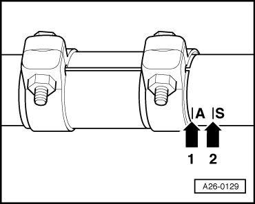
→ Fig.1    Installation position of front clamp

  • ‒ Position clamp about 5 mm away from the relevant marking line.
  • ◆ Arrow 1 - vehicles with automatic gearbox
  • ◆ Arrow 2 - vehicles with manual gearbox

 
A26-0159
  • ‒ → Install the clamps so that the ends of the bolts do not protrude over the lower edge of the clamping sleeve.
    • ‒ Bolted connection facing to the left
 
A26-0159

→ Fig.2    Installation position of rear clamp

  • ‒ Install the clamping sleeve so that the ends of the bolts do not protrude over the lower edge of the clamping sleeve.
    • ‒ Bolted connection facing to the front

 
A26-0154

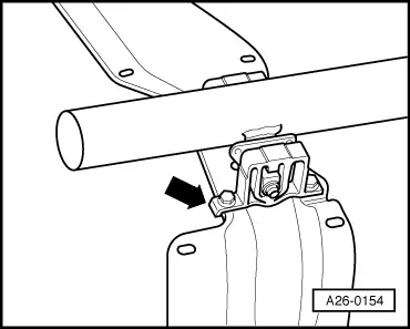
→ Fig. 3    Installation position of mounting

Angled end at base of mounting -arrow- faces in direction of travel.

Separating centre and rear silencers > < Checking cooling system for leaks