audi Workshop Repair Guides

Audi Workshop Service and Repair Manuals

Checking combination valve for secondary air inlet for function and leaks > < Checking secondary air inlet valve -N112
4-cylinder Engine (2-valve), Mechanical Components
Secondary air system - vehicles with engine code APF
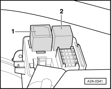
Checking secondary air pump relay -J299 and actuation
 
G24-0023

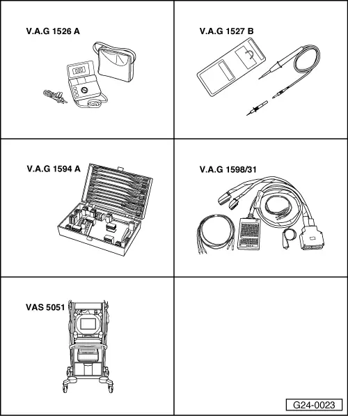
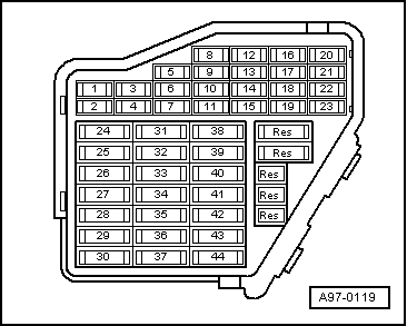
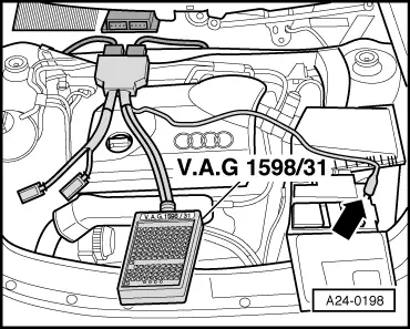
Special tools and workshop equipment required

  • ◆ V.A.G 1526 A
  • ◆ V.A.G 1527 B
  • ◆ V.A.G 1594 A
  • ◆ V.A.G 1598/31
  • ◆ VAS 5051 with VAS 5051/1
 
A01-0122

Test sequence

  • ‒ Connect vehicle diagnostic, testing and information system VAS 5051 and select vehicle system "01 - Engine electronics". For this purpose, the ignition must be switched on.

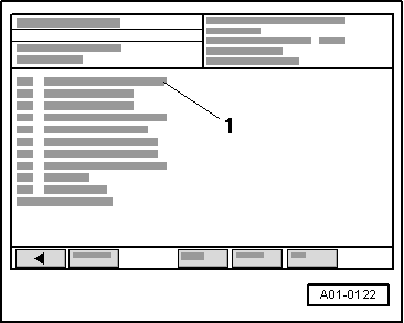
=> Simos Fuel Injection and Ignition System; Repair group 01

→ Display on VAS 5051:

  • ‒ Under -1- select the diagnostic function "03 - Final control diagnosis".

 
A24-0341
  • ‒ Actuate the secondary air pump relay -J299.
    • ‒ → The relay for secondary air pump -1- (under cover on left on the bulkhead) must tighten and the engine for the secondary air pump -V101 must start in intervals.
  • ‒ Exit function "03 - Final control diagnosis" by pressing the ◂ key.
  • ‒ Press "06 - End output".
  • ‒ Switch ignition off.

A - If relay does not respond:

  • ‒ Check voltage supply of secondary air pump relay .
  • ‒ Check activation of secondary air pump relay => Page 26-69.

B - If relay responds but secondary air pump motor does not run:

  • ‒ Check voltage supply of secondary air pump relay => Page 26-71.
 
A26-0311

Checking voltage supply of secondary air pump relay

  • ‒ Detach secondary air pump relay.
  • ‒ → Connect multimeter as follows to measure voltage.

Relay carrier under left cover at the bulkhead
Contact

Measure to

1

Engine earth

    • ‒ Specification: approx. battery voltage
 
A97-0116

If specification is not attained:

  • ‒ Carry out the following tests (marked with dots):
  • ● → Check fuse S131 (50 A) in main fuse box/battery.
  • ● Check wiring from battery + (terminal 30) to fuse S131 for secondary air pump relay -J299 (under the left cover at the bulkhead) for open circuit using the current flow diagram.
  • ‒ Eliminate open circuit using the current flow diagram.
 
A26-0311
  • ‒ → Connect multimeter as follows to measure voltage.

Relay carrier under left cover at the bulkhead
Contact

Measure to

3

Engine earth

  • ‒ Operate starter briefly.
    • ‒ Specification: approx. battery voltage
  • ‒ Switch ignition off.
 
A97-0119

If specification is not attained:

  • ‒ Carry out the following tests (marked with dots):
  • ● → Check fuse S243 (in fuse box, terminal 43).
  • ● Check for open circuit in wiring from secondary air pump relay -J299 (under left cover at bulkhead) via fuse S243 (in fuse box, position 43) to fuel pump relay using the current flow diagram.
  • ‒ Eliminate open circuit using the current flow diagram.
 
A26-0311

Checking actuation of secondary air pump relay

  • ‒ Detach secondary air pump relay.
  • ‒ → Connect voltage tester V.A.G 1527 B as follows:

Relay carrier under left cover at the bulkhead
Contact

Measure to

4

Battery positive

 
A01-0122

→ Display on VAS 5051:

  • ● Vehicle diagnostic, testing and information system VAS 5051 connected, vehicle self-diagnosis and vehicle system "01 - Engine electronics" selected. For this purpose, the ignition must be switched on.
  • ‒ Under -1- select the diagnostic function "03 - Final control diagnosis".
  • ‒ Actuate the secondary air pump relay -J299.
    • ‒ The LED should flash.
  • ‒ Exit function "03 - Final control diagnosis" by pressing the ◂ key.
  • ‒ Switch ignition off.
 
A24-0198

If LED does not flash:

  • ‒ → Connect the V.A.G 1598/31 test box to wiring harness connectors; the engine control unit should not be connected. Attach the earth clip of test box to earth -arrow-.

=> Simos Fuel Injection and Ignition System; Repair group 24

Important
To prevent damage to the electronic components, select appropriate measuring range before connecting the measuring cables and observe the test requirements.
 
A26-0311
  • ‒ → Check for open circuit and short to positive or earth in the following wiring connection:

Relay carrier under left cover at the bulkhead
Contact

Test box V.A.G 1598/31
Socket

4

72

  • ‒ Use current flow diagram to eliminate open circuit in wiring/short circuit.

If no fault is found:

  • ‒ Replace secondary air pump relay -J299.
 
A10-0885

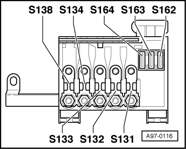
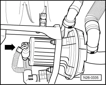
Checking voltage supply for secondary air pump motor

  • ‒ → Remove engine cover -arrows-.

 
N26-0335
  • ‒ → Unplug connector -arrow- at secondary air pump motor -V101.
 
A24-0331
  • ‒ → Connect voltage tester V.A.G 1527 B between contacts 1 and 2.

 
A01-0122
  • ● Vehicle diagnostic, testing and information system VAS 5051 connected, vehicle self-diagnosis and vehicle system "01 - Engine electronics" selected. For this purpose, the ignition must be switched on.

→ Display on VAS 5051:

  • ‒ Under -1- select the diagnostic function "03 - Final control diagnosis".
  • ‒ Actuate the secondary air pump relay -J299.
    • ‒ The LED should flash.

If LED does not flash:

  • ‒ Carry out the following tests (marked with dots):
  • ● Check for open circuit in wiring from contact 1 of connector to secondary air pump relay -J299 (in relay carrier under left cover at bulkhead) using the current flow diagram.
  • ● Check for open circuit in wiring between contact 1 of the connector to earth using the current flow diagram.
  • ‒ Eliminate open circuit using the current flow diagram.

If no fault is found:

  • ‒ Replace the secondary air pump => page 26-80.

Checking combination valve for secondary air inlet for function and leaks > < Checking secondary air inlet valve -N112