
A3 Mk1
| Removing and installing toothed belt |
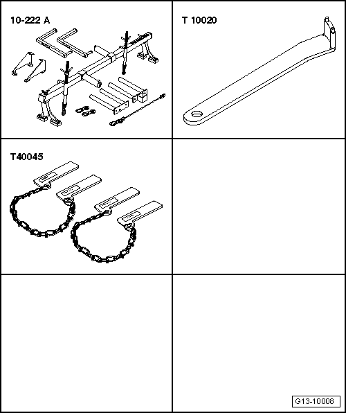
| Special tools and workshop equipment required |
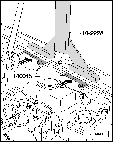
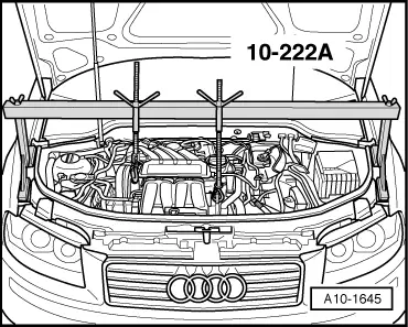
| t | Support bracket -10-222 A- |
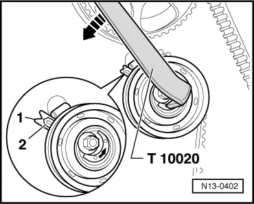
| t | 2-hole pin wrench -T10020- |
| t | Mud wing compensation plate -T40045- |
|
|
 Note
Note |
|
|
|
|
|
|
|
|
|
|
|
|
|
|
|
Note
|
|
|
|
|
|
|
|
|
|
Note
|
|
|
|
|
|
|
|
|
|
|
|
| Component | Nm | ||||||
| Toothed belt tensioning roller to cylinder head | 23 | ||||||
| Toothed belt cover (bottom) to cylinder block | 10 1) | ||||||
| Toothed belt cover (centre) to cylinder block | 10 1) | ||||||
| Engine support to cylinder block | 45 | ||||||
| Engine mounting to body | 40 + 90° 2)3) | ||||||
| Connecting bracket to body/engine mounting | 25 | ||||||
| Tensioner for poly V-belt to bracket for ancillaries | 23 | ||||||
| Splash plate to bracket for ancillaries | 23 | ||||||
| |||||||