| –
| Keep touching the → key until the following display appears: |
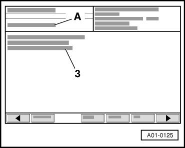
| A - | 3rd control element in test |
| 3 - | Exhaust gas recirculation valve -N18- |
| A - | Actuator is running; continued switching is allowed |
| l
| LED should flash slowly. |

Note | Voltage testers with a low current draw do not go out completely between activation signals from engine control unit, but continue to glow slightly and become distinctly brighter on activation. |
| –
| Exit function “03 - Final control diagnosis” by pressing the ← key. |
| –
| Press “06 - End output”. |
| If the LED does not flash: |
| –
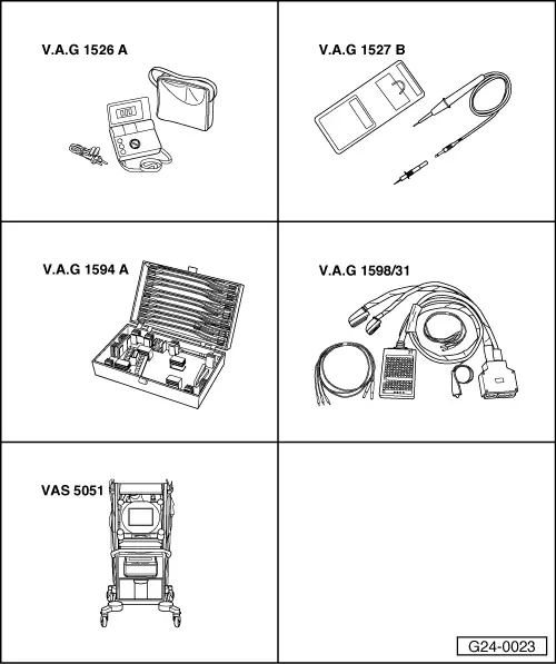
| Connect adapter cable, 121-pin -V.A.G 1598/31- (test box) to connectors of wiring harness; do not connect engine control unit. Connect earth clip of test box to earth → Rep. Gr.24. |

Caution | To avoid damage to the electronic components, select the required measuring range and observe test conditions before connecting the test leads. |
|
|
|
|