audi Workshop Repair Guides

Audi Workshop Service and Repair Manuals

Reworking valve seats > < Removing, installing and tensioning toothed belt
4-Cylinder engine (2-valve, roller rockers), Mechanics
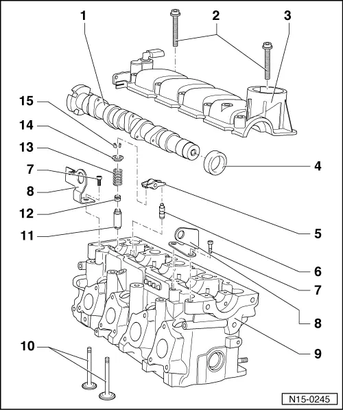
Servicing valve gear
 
N15-0245

Notes:

  • ◆ Cylinder heads which have cracks between the valve seats or between the valve seat inserts and the spark plug thread can be used further without reducing service life, provided the cracks do not exceed a maximum of 0.5 mm in width, or when no more than the first few turns of the spark plug threads are cracked.
  • ◆ All bearing and running surfaces must be oiled before assembling.
  • Camshaft
    • ◆ Checking axial clearance
    • ◆ Removing and installing
      => Page 15-47
    • ◆ Check radial clearance with Plastigage
      Wear limit: 0.1 mm
    • ◆ Run-out: max. 0.05 mm
    • ◆ Identification
      => Page 15-39, Fig.2
 
N15-0245
  • 6 Nm + 1/4turn (90 °) further
    • ◆ Renew
    • ◆ Note installation instructions and sequence when loosening and tightening => Page 15-47
  • Cylinder head cover
    • ◆ Reworking the sealing surface is not permitted
    • ◆ With integrated camshaft bearings
    • ◆ Remove remnants of old sealant
    • ◆ Coat with AMV 188 001 02 before fitting
    • ◆ Install vertically from above with dowel pins in holes in cylinder head
    • ◆ Removing and installing
      => Page 15-47
 
N15-0245
  • Oil seal
    • ◆ Lightly oil sealing lip of oil seal
    • ◆ Renew=> Page 15-44
  • Roller rocker finger
    • ◆ Check roller bearing
    • ◆ Oil contact surface
    • ◆ Use securing clip to clip onto support element when installing
  • Support element
    • ◆ Do not interchange
    • ◆ With hydraulic valve clearance compensation
    • ◆ Oil contact surface
  • 20 Nm + 1/4 turn (90 °) further
    • ◆ Renew
  • Bracket/lifting eye
 
N15-0245
  • Cylinder head
    • ◆ Reworking of camshaft side sealing surface is not permitted
    • ◆ Reworking valve seats
      => Page 15-41
    • ◆ Reworking sealing surface, cylinder block side => Fig. 1
  • Valves
    • ◆ Do not rework only grinding-in is permitted
    • ◆ Valve dimensions => Fig. 3
  • Valve guide
    • ◆ Checking => Page 15-54
    • ◆ Repair valve guide has a collar
  • Valve stem seal
    • ◆ Renewing=> Page 15-55
 
N15-0245
  • Valve spring
    • ◆ Removing and installing:
      Cylinder head
      removed: with 2037
      installed: => Page 15-55, renewing valve stem seals
  • Upper valve spring plate
  • Cotters
 
N15-0318

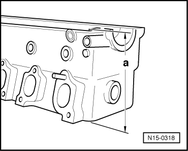
→ Fig. 1    Reworking cylinder head sealing surface, cylinder block side

Cylinder head reworking dimension:
    a = At least 135.6 mm

Checking camshaft axial clearance

 
W00-0037

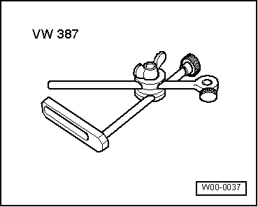
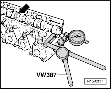
Special tools, workshop equipment, testers, measuring instruments and auxiliary items required

  • ◆ → VW 387 Universal dial gauge bracket
  • ◆ Dial gauge
 
N15-0317
  • ‒ → Checking camshaft axial clearance

Check with support elements and cylinder head cover removed.

  • ‒ Pull camshaft seal off with 3364. Pre-load camshaft at centre bearing -arrow- using thumb pressure and check axial clearance by moving camshaft to and fro.

Wear limit: max. 0.15 mm

 
N15-0319

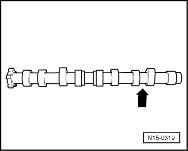
→ Fig.2    Camshaft identification

Marking between number 1 cylinder inlet and exhaust cams

Cylinder 1 -arrow-

032 AD

 
V15-0024

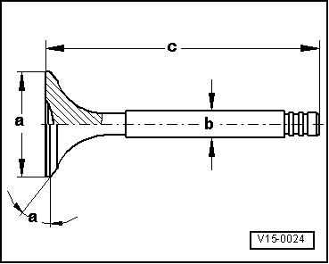
→ Fig. 3    Valve dimensions

Note:

Valves must not be reworked. Only lapping-in is permitted.

Dimension

Inlet valve

Exhaust valve

øa

mm

34.5

28.0

øb

mm

5.98

5.96

c

mm

99.25

99.25

α

45

45

Reworking valve seats > < Removing, installing and tensioning toothed belt