audi Workshop Repair Guides

Audi Workshop Service and Repair Manuals

Enginecrankshaft group, pistons > < Installing
4-Cylinder engine (5-valve), Mechanics
Adjusting engine mountings
 
W00-0225

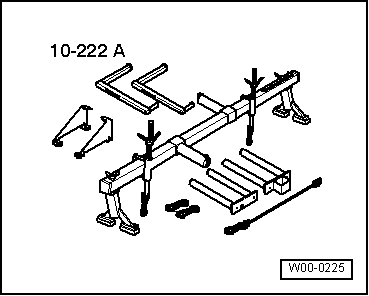
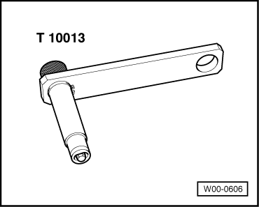
Special tools and workshop equipment required

  • ◆ 10-222 A engine support

 
W00-0606
  • ◆ Retainer T10013
 
A10-1321

Checking adjustment

  • ‒ → Remove engine cover panel -arrows-.

 
A13-0435
  • ‒ → Disconnect coolant expansion tank -1- and fluid reservoir for power steering -2-. The hoses remain connected.

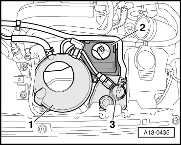
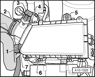
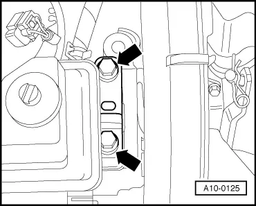
Note:

The ACF container -3- does not have to be removed.

 
A10-0425
    • ‒ → Both bolt-heads -b- must align flush with edge of support arm -2-.
    • ‒ Distance -a- between engine console -1- and support arm -2- of right engine mount should be 13 mm.
  • Check distance -a- by inserting a 12 mm flat iron bar (alternatively, use special tool 2011). It should slide in easily.

 
A10-1322

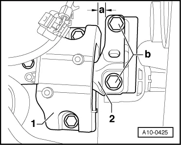
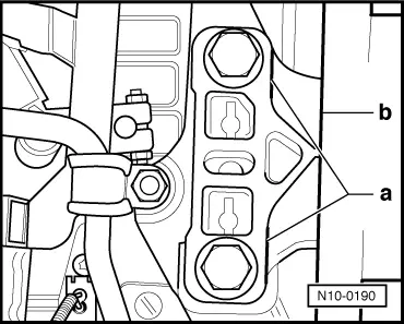
If the gap is too narrow or too wide, proceed as follows:

  • ‒ → Disconnect secondary air pump intake hose -1- from air cleaner housing.
  • ‒ Unscrew bolt -7-.
  • ‒ Disconnect air hose -2- from air mass meter.
  • ‒ Unplug connector -3- from air mass meter.
  • ‒ Unscrew bolts -5- and -6-.
  • ‒ Remove air cleaner housing and pull off vent hose -4- from behind.
 
A10-1330
  • ‒ → Insert the retainer T10013 in the lifting eye (right side) and lock into place by positioning the washer off centre.

 
A10-1257
  • ‒ → Set up engine support bracket 10-222 A in front of gas strut on bolted flanges of wing panels with spindles at front.
  • ‒ Engage spindle hooks into respective lifting eye or retainer T10013.
  • ‒ Raise the engine slightly, taking up the weight evenly on both spindles.
 
A10-0125
  • ‒ → Unscrew the bolts -arrows- in the support arm at the engine...

 
A10-0126
  • ‒ → ... and on the gearbox. Replace all 4 bolts (if not already done so when installing engine) and tighten by hand.
 
A10-0425
  • ‒ → Slacken bolts -b- on left and right-hand support arms by about two turns each.
  • ‒ Insert an iron bar between engine console -1- and support arm -2-, then move engine until gap -a- measures 13 mm.
    • ‒ a 12 mm flat iron bar (alternatively special tool 2011 ) should slide in easily.
    • ‒ both bolt-heads -b- should align flush with edge of support arm.
  • ‒ Tighten bolts -b- in support arm at engine to 60 Nm + 90°.

 
N10-0190
  • ‒ → Make sure that the edges of the support arm -a- and the gearbox console -b- align parallel.
  • ‒ Tighten bolts in support arm at gearbox to 60 Nm + 90°.

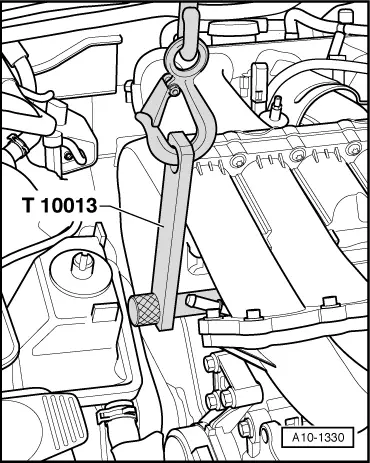
Install in reverse sequence; note the following points:

Note:

To remove the retainer T10013 the securing washer must be raised with a screwdriver.

Enginecrankshaft group, pistons > < Installing