
A3 Mk1
|
Removing and installing engine
Removing
Notes:
Caution!
On vehicles equipped with telematics the telematics control unit must be switched to service mode before the battery terminals are disconnected.=>Radio, telephone and navigation system; Repair group 91
|
 |
|
|
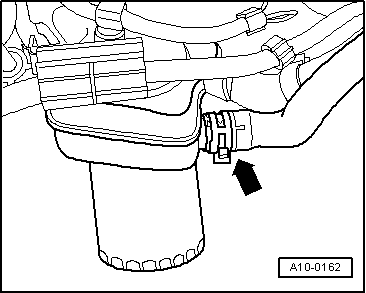
Warning!
Hot steam or hot coolant can escape when the cap on the expansion tank is opened. Cover the cap with a cloth, and open it carefully.
|
 |
|
|
 |
|
|
 |
|
|
 |
|
|
 |
|
|
 |
|
|
 |
|
|
 |
|
|
 |
|
|
 |
|
|
 |
|
|
 |
|
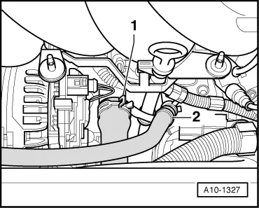
Note: In the picture shown on vehicle with automatic gearbox. |
 |
|
|
Vehicles with automatic gearbox
|
 |
|
|
All models
Vehicles with manual gearbox:
|
 |
|
|
All models
|
 |
|
|
 |
|
|
 |
|
|
 |
|
|
Vehicles with manual gearbox (until approx. 07/98):
|
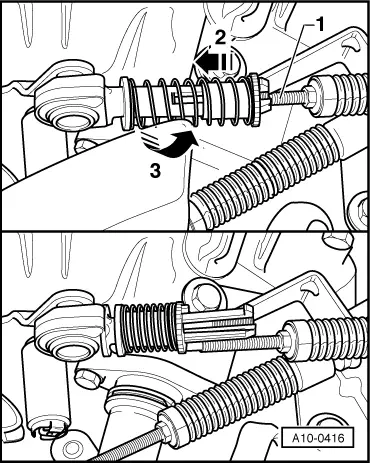 |
|
|
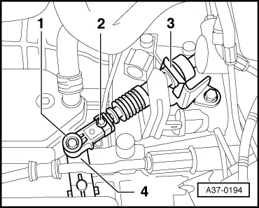
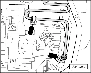
Vehicles with manual gearbox (from approx. 08/98): Disconnect both selector cables at gearbox as follows:
|
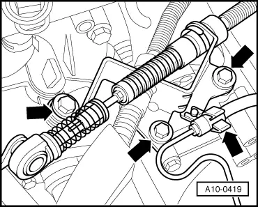 |
|
|
All vehicles with manual gearbox:
|
 |
|
|
 |
|
Note: Do not depress clutch pedal after removing slave cylinder. |
 |
|
|
Vehicles with automatic gearbox
|
 |
|
|
 |
|
|
All models
|
 |
|
|
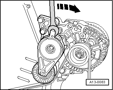
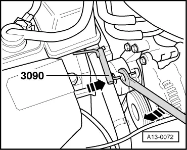
Note: Before removing the ribbed belt, mark the direction of rotation with chalk or a felt pen. If a used belt rotates in the wrong direction when refitted, it can break.
|
 |
|
|
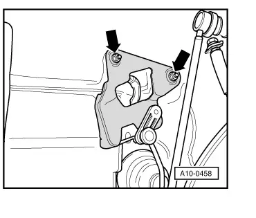
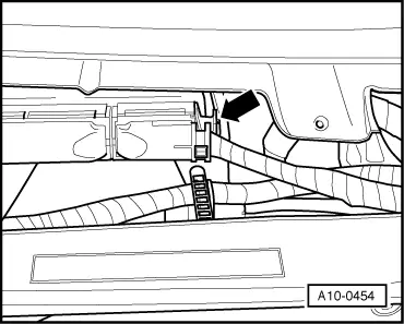
Note: → The tensioning element must be secured with a suitable pin or mandrel of4.5 mm dia. and about 55 mm long. On vehicles without headlight washer system conrod support 3090 may also be used. |
 |
|
|
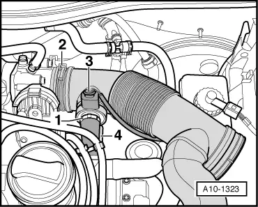
Warning
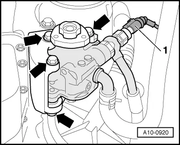
Fuel system is under pressure. Before opening the system place a cloth around the connection. Then release pressure by carefully loosening the connection.
|
 |
|
|
 |
|
|
 |
|
|
 |
|
|
Vehicles with manual gearbox
|
 |
|
|
All models
|
 |
|
|
 |
|
|
 |
|
|
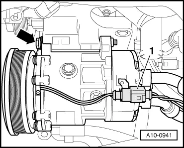
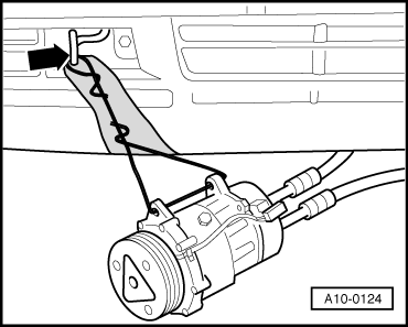
Vehicles with air conditioner:
Warning!
The air conditioning system refrigerant circuit must not be opened.
|
 |
|
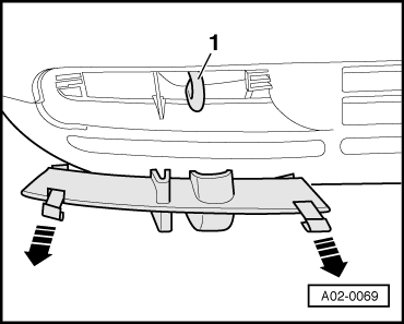
Note: Use adhesive tape to prevent scratching bumper. |
 |
|
 |
|
|
 |
|
|
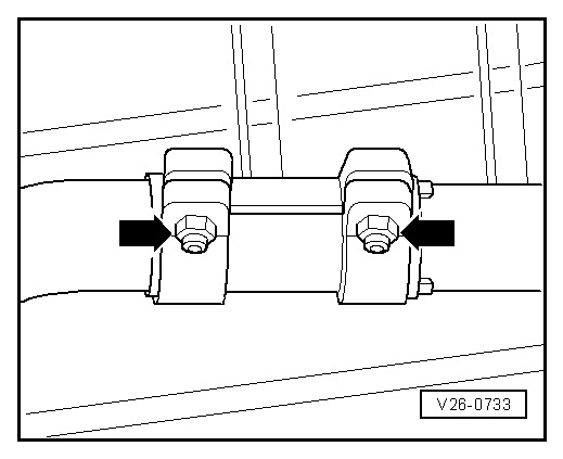
Note: The flexible pipe connection (de-coupling element) on the front exhaust pipe must not be bent more than 10 °- otherwise it can be damaged.
|
 |
|
|
 |
|
 |
|
Note: Use adhesive tape to prevent scratching bumper.
|
 |
|
|
 |
|
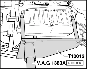
Note: Use step ladder VAS 5085 for access to engine compartment from above. |
|
|
|
|
|
Notes:
|