audi Workshop Repair Guides

Audi Workshop Service and Repair Manuals

Removing and installing upper section of intake manifold > < Piston and cylinder dimensions
4-Cylinder engine (5-valve), Mechanics
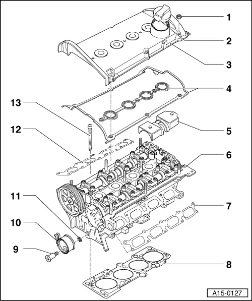
Removing and installing cylinder head

Notes:

  • ◆ The following procedures are described for vehicles with electronic throttle, secondary air system and exhaust gas recirculation system. The procedures for older vehicles without these features are the same, except that some of the steps will not be required.
  • ◆ Renew the cylinder head bolts.
  • ◆ When performing repairs, renew seals, gaskets, self-locking nuts and bolts which have a specified tightening angle.
  • ◆ When installing an exchange cylinder head with the camshafts fitted, the contact surfaces between bucket tappet and cam running surface must be oiled after installation of the cylinder head.
  • ◆ The plastic protectors fitted to protect the open valves must only be removed immediately before fitting the cylinder head.
  • ◆ When fitting a new cylinder head or cylinder head gasket, drain off all the old coolant and re-fill with new coolant.
  • ◆ Cylinder heads which have cracks between the valve seats or between valve seat inserts and the spark plug thread can be used further without reducing service life, provided the cracks do not exceed a maximum of 0.3 mm in width, or when no more than the first 4 turns of the spark plug threads are cracked.
 
A15-0127

Part I

  • 10 Nm
    • ◆ Start with inner nuts
    • ◆ Tighten outer nuts crosswise diagonally
  • Filler cap
    • ◆ Renew seal if damaged
  • Cylinder head cover
    • ◆ Removing and installing
  • Cylinder head cover gasket
    • ◆ Renew if damaged or leaking
    • ◆ Before fitting gasket apply sealant compound to corner locations of flange
      => Figs.15-9
    • ◆ Liquid sealant

=> Parts List

 
A15-0127
  • Oil deflector
    • ◆ Note installation position
  • Cylinder head
    • ◆ Removing => Page 15-25
    • ◆ Check for distortion
      => Fig. 15-8
    • ◆ Reworking limit
      => Fig.15-8
    • ◆ Installing => Page 15-30
    • ◆ After replacing, fill with fresh coolant
  • Gasket
    • ◆ For lower section of intake manifold
    • ◆ Different versions possible

=> Parts List

    • ◆ Renew
  • Cylinder head gasket
    • ◆ Renew => Removing cylinder head, Page 15-25
    • ◆ Installation position: part No. faces cylinder head and must be legible from inlet side
    • ◆ After replacing, fill with fresh coolant
 
A15-0127
  • 45 Nm
  • Tensioner
  • Washer
  • Gasket
    • ◆ For exhaust manifold
    • ◆ Note installation position
    • ◆ Renew
  • Cylinder head bolt
    • ◆ Renew
    • ◆ Note sequence when loosening
      => Page 15-29
    • ◆ Note sequence when tightening
      => Page 15-33
 
A15-0781

Part II

Note:

The figure shows the intake manifold version fitted as from 08.97.

  • Fuel supply pipe
    • ◆ Mark pipe before disconnecting
  • Fuel return pipe
    • ◆ Mark pipe before disconnecting
  • 22 Nm
  • Support
    • ◆ For upper section of intake manifold
  • 10 Nm
  • Washer
  • Rubber bush
 
A15-0781
  • 10 Nm
  • Earth wire
  • 10 Nm
  • Intake manifold - upper section
    • ◆ Removing and installing
      => Page 15-10
  • Seal
    • ◆ Renew
  • Throttle valve housing
  • 10 Nm
  • Gasket
    • ◆ Renew
  • 10 Nm
  • Fuel rail
    • ◆ With fuel injectors
 
A15-0781
  • O-ring
    • ◆ For injectors
    • ◆ Renew
    • ◆ Lubricate with clean engine oil
  • 10 Nm
  • Intake manifold - lower section
    • ◆ Removing and installing
      => Page 15-17
  • Bracket
    • ◆ For oil dipstick guide tube
  • 10 Nm
  • Gasket
    • ◆ Renew
 
V15-0654

→ Fig. 1    Checking cylinder head for distortion

  • ‒ Use knife-edge straightedge and feeler gauge to measure at several points.
    • ‒ Max. permissible distortion: 0.1 mm

 
A15-0169

→ Fig.2    Cylinder head reworking limit

  • ‒ Reworking the cylinder head (skimming) is only permitted down to minimum dimension a.
    • ‒ Minimum dimension a = 139.20 mm
 
A15-0137

→ Fig. 3    Sealing transition points between double bearing cap and cylinder head

  • ‒ Apply a small quantity of sealant to flange corner points -arrows- on upper sealing surface of cylinder head.
    • ‒ Sealant

=> Parts catalogue

 
A15-0138

→ Fig. 4    Sealing points for camshaft adjuster / cylinder head

  • ‒ Apply a small quantity of sealant to flange corner points -arrows- on upper sealing surface of cylinder head.
    • ‒ Sealant

=> Parts catalogue

Removing and installing upper section of intake manifold > < Piston and cylinder dimensions