
A3 Mk1
|
Secondary air system - vehicles with engine code letters APG
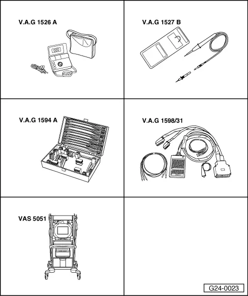
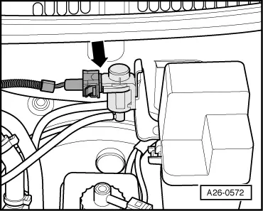
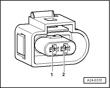
Testing secondary air inlet valve -N112
|
 |
|
|
If the display shows a fault relating to secondary air inlet valve -N112:
|
 |
|
|
 |
|
|
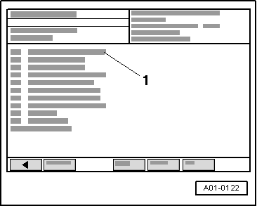
→ Display on VAS 5051:
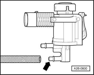
If the valve does not open and close properly:
|
|
|
|
If valve does not click during final control diagnosis: Testing internal resistance
|
 |
|
If the specification is not attained:
If the specification is obtained: Checking voltage supply Requirements for test:
=> Current flow diagrams, Electrical fault finding and Fitting locations binder
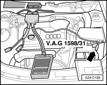
Note: The secondary air inlet valve -N112 receives its power supply via the fuel pump relay. |
 |
|||||
If the LED does not light up:
=> Current flow diagrams, Electrical fault finding and Fitting locations binder
|
|
|
|
If the LED lights up: Checking activation
|
|
|
|
→ Display on VAS 5051:
|
 |
|
|
If the LED lamp does not flash or if it lights up continuously:
|
|
|||||
If the wiring is OK:
|