audi Workshop Repair Guides

Audi Workshop Service and Repair Manuals

Removing and installing air mass meter > < Accelerator mechanism on right-hand drive vehicles without accelerator pedal module - exploded view
Adjusting accelerator position senderG79 - right-hand drive vehicles without accelerator pedal module
Adjusting accelerator position sender -G79- - right-hand drive vehicles without accelerator pedal module
The accelerator position sender -G79- must be adjusted after removing and installing either the accelerator position sender -G79- or the cable cam.
Special tools and workshop equipment required
   
t  Vehicle diagnostic, testing and information system -VAS 5051B-
  W00-10343
Procedure
l  Tightening torque → Chapter.
–  Bolt accelerator position sender -G79- into bracket (removed earlier) → Item.
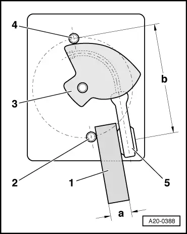
–  Using a strip of sheet metal, make up adjuster tool -1- (with dimension -a-).
l  Dimension -a- = 13.25 mm.
–  Fit cable cam -3- loosely on shaft of accelerator position sender.
–  Bring adjuster tool into contact with thread of lower securing bolt -2-.
–  Bring cable eye -5- of cable cam into contact with adjuster tool -1-, as shown in illustration.
–  With components in this position, measure distance between centre of cable eye and top securing bolt -4-. Make sure cable on cable cam is taut while measuring.
–  Adjust according to distance -b-.
l  Distance -b- = 65.59 mm.
–  Secure cable cam in this position.
–  Install accelerator position sender -G79- and bracket in vehicle.
Vehicles with automatic gearbox:
–  Remove accelerator pedal stop from vehicle floor and in its place bolt on accelerator pedal stop for vehicles with manual gearbox.
l  Accelerator pedal stops for vehicles with manual gearbox: black
l  Accelerator pedal stops for vehicles with automatic gearbox: grey
  A20-0388
All vehicles (continued):
–  With ignition switched off, connect vehicle diagnostic, testing and information system -VAS 5051B- with diagnosis lead to diagnosis connection.
–  Start the engine and run at idling speed.
Display on -VAS 5051B-:
–  Select Vehicle self-diagnosis from the list -item 1-.
  A01-10029
Display on -VAS 5051B-:
–  From menu -1-, select vehicle system “Engine electronics” and press key to continue.
  A01-10008
Display on -VAS 5051B-:
–  From menu -1-, select diagnosis function “Measured values” and press key to continue.
  A01-10024
Display on -VAS 5051B-:
–  Press keys 62 on keypad -1- to select “Display group 062” and confirm entry by pressing Q key.
  A01-10026
Display on -VAS 5051B-:
–  Check display in display zone -3-.
–  Press accelerator all the way down and hold in position.
l  Specification: 72 ... 74 % (accelerator pedal depressed)
–  If specification is not attained, check installation position of cable cam and adjust if necessary → Anchor.
–  Check adjustment again:
–  Press accelerator pedal down slowly.
l  Specification: The readout in the display should increase steadily unit it reaches 72 ... 74 % (accelerator pedal fully depressed).
–  Press key to terminate function “Measured values”.
  A01-10027
Display on -VAS 5051B-:
–  From menu -1-, select function “End output” and press key to continue.
–  Switch off ignition and unplug diagnostic connector.
Vehicles with automatic gearbox:
–  Reinstall accelerator pedal stop for vehicles with automatic gearbox in vehicle floor.
–  Then check kick-down switch -F8-:
  A01-10024
Display on -VAS 5051B-:
–  From menu -1-, select vehicle system “Gearbox electronics” and press key to continue.
  A01-10008
Display on -VAS 5051B-:
–  From menu -1-, select diagnosis function “Measured values” and press key to continue.
  A01-10024
Display on -VAS 5051B-:
–  Press key 1 on keypad -1- to select “Display group 001” and confirm entry by pressing key Q.
  A01-10026
Display on -VAS 5051B-:
–  Check display in display zone -4-.
–  Press accelerator pedal all the way down to full-throttle position.
l  Specification: XXX0 XXXX.
–  Press accelerator pedal all the way down past kick-down point.
l  Specification: XXX1 XXXX.
  Note
Switching inputs at the locations marked “X” can be ignored during this test.
–  Repeat adjustment procedure if specification is not attained.
–  Press key to terminate function “Measured values”.
  A01-10027
Display on -VAS 5051B-:
–  From menu -1-, select function “End output” and press key to continue.
–  Switch off ignition and unplug diagnostic connector.
  A01-10024

Removing and installing air mass meter > < Accelerator mechanism on right-hand drive vehicles without accelerator pedal module - exploded view