
A3 Mk1
| Fuel delivery unit, fuel gauge senders and suction-jet pump - exploded view |
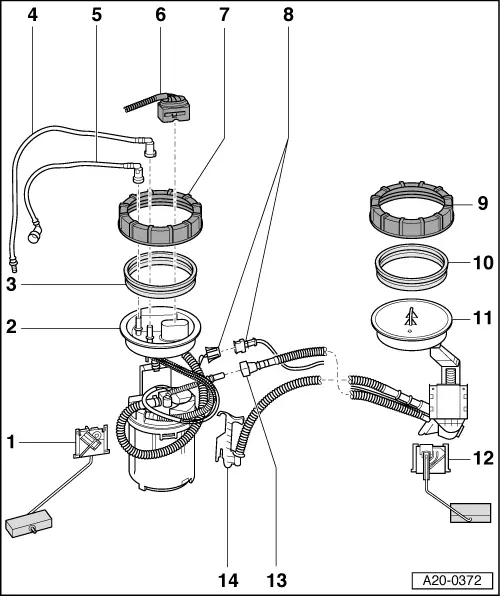
| 1 - | Fuel gauge sender -G- |
| q | Checking resistance values → Chapter |
| q | Removing and installing → Chapter |
| 2 - | Fuel delivery unit |
| q | With flange |
| q | Checking fuel pump (electrical test) → Chapter |
| q | Checking residual pressure → Rep. Gr.24 |
| q | Removing and installing → Chapter |
| q | Put at least 5 litres of fuel into tank after installing |
| 3 - | Seal |
| q | Renew |
| q | When installing, fit seal (dry) in opening in fuel tank |
| 4 - | Fuel return pipe |
| q | Blue |
| q | From fuel rail |
| q | Attached to connection marked “R” on flange |
| q | To disconnect from flange, press release tab on connection |
| 5 - | Fuel supply pipe |
| q | Black |
| q | To fuel filter |
| q | Attached to connection marked “V” on flange |
| q | To disconnect from flange, press release tab on connection |
| 6 - | Electrical connector |
| q | For fuel pump, fuel gauge sender -G- and fuel gauge sender 2 -G169- |
| 7 - | Union nut |
| q | 80 Nm |
| q | Loosen and tighten with union nut tool -3217- |
| 8 - | Electrical connector |
| q | For fuel gauge sender 2 -G169- |
| 9 - | Union nut |
| q | 80 Nm |
| q | Loosen and tighten with union nut tool -3217- |
| 10 - | Seal |
| q | Renew |
| q | When installing, fit seal (dry) in opening in fuel tank |
| 11 - | Suction-jet pump |
| q | With pipes |
| q | Only available together with -item 12-. |
| q | Removing and installing → Chapter |
| q | Put at least 5 litres of fuel into tank after installing |
| 12 - | Fuel gauge sender 2 -G169- |
| q | Only available together with -item 11-. |
| q | Checking → Chapter |
| q | Removing and installing → Chapter |
| 13 - | Hose connection |
| q | Connects fuel hose to suction-jet pump |
| q | Press release tab to disconnect |
| 14 - | Retainer |
| q | Retains fuel hose (coming from suction-jet pump) |
| q | Hook into fuel delivery unit and press in until it engages |