audi Workshop Repair Guides

Audi Workshop Service and Repair Manuals

TDI®injection and glow plug system (4-cyl. unit injector) > < Checking the knock sensors
Motronic fuel injection and ignitionsystem (4-cyl. turbo)
Checking ignition system
Checking the Hall sensor

The Hall sensor indicates the ignition position for cylinder 1.

If the Hall sensor fails to function, the knock control is switched off and the ignition timing is retarded slightly because the signals can no longer be assigned to the cylinders.

Even without a signal from the Hall sensor, the engine will continue to run and can also be re started.

  • ◆ When a fault is detected, the engine control unit produces one spark for each cylinder on every crankshaft revolution.
  • ◆ The fact that the control unit is out of phase by one engine revolution does not have any noticeable effect on the injection system. If this happens, the fuel is injected "upstream" (before the closed inlet valve) instead of while the inlet valve is open. This has only a negligible influence on the quality of the air/fuel mixture.

Note on signal testing with an oscilloscope:

The centre point of the window of the Hall sensor must lie on the third trailing edge of the engine speed signal after the reference mark gap.

 
V96-0836
  • ‒ Push back the rubber sleeve on the Hall sensor connector.
  • ‒ → Connect the V.A.G 1527 diode test lamp to contacts 1 and 2 on the Hall sensor connector from behind (the connector remains attached to the Hall sensor).

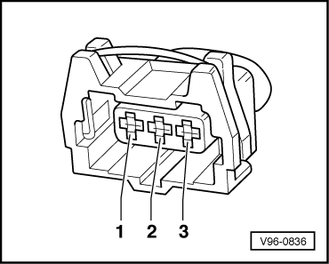
Note:

The connector contacts are numbered on the back of the connector.

  • ‒ Operate the starter for a few seconds.

The diode test lamp must flash briefly on each second engine revolution.

If the diode test lamp does not flash:

Check the power supply for the Hall sensor

  • ‒ Unplug the connector from the Hall sensor.
  • ‒ Switch on the ignition.
 
V96-0836
  • ‒ → Connect the V.A.G 1526 hand held multimeter for voltage measurement contact 1 on the connector and the engine earth.
  • Specified value: 4,5 ... 5.5 V.

Checking the signal wire for Hall sensor

  • ‒ → Connect the V.A.G 1526 hand held multimeter between contact 2 on the connector and the engine earth.
  • Specified value: approx battery voltage.

Checking the earth wire for the Hall sensor

  • ‒ Connect the V.A.G 1526 hand held multimeter for resistance measurement between contact 3 on the connector and the engine earth.
  • Specified value: Continuity

If the specified values are all achieved and the diode test lamp does not flash (measured between contacts 1 and 2 with starter connector attached),
replace the Hall sensor.

If the specified values are not achieved:

Check the wiring between the Hall sensor and engine control unit

 
V96-0836
  • ‒ Connect the V.A.G 1598/22 test box to the wiring harness for the engine control unit
    =>Page 24-8.
  • ‒ → Check the wiring from the Hall sensor ...
  • ‒ ... to the engine control unit for an open circuit and short to positive or earth.

3-pin connector on the wiring harness contact

Test box V.A.G 1598/22 contact

1 (positive)

62

2 (signal)

76

3 (earth)

67

  • ‒ If necessary, rectify open circuit or short circuit.
  • ‒ If a trial erasure of the fault memory is followed by the renewed indication of a fault relating to the camshaft sensor (Hall sensor) although all previous tests were OK, the following faults are possible:
    • ‒ Rotor ring for Hall sensor misaligned.
  • ‒ Unbolt the Hall sensor, then check to ensure that the rotor ring is correctly aligned on the camshaft.(if it is incorrectly installed, the catch will be pressed flat when the securing screw is tightened).
  • ‒ If the position of rotor ring is OK, check the position of the camshaft in relation to the crankshaft.

=> 4- Cylinder Engine, Mechanics; Repair Group 15; Cylinder head, valve gear; Remove and install camshafts and camshaft adjustment

Note on signal testing with an oscilloscope:

The centre point of the window of the Hall sensor must lie on the third trailing edge of the engine speed signal after the reference mark gap.

TDI®injection and glow plug system (4-cyl. unit injector) > < Checking the knock sensors